Lo Plate Voltage: Opinions needed

Recording Techniques, People Skills, Gear, Recording Spaces, Computers, and DIY

Moderators: drumsound, tomb

User avatar
paully
pushin' record
Posts: 223
Joined: Mon Apr 09, 2007 8:20 am
Location: Northern New Jersey

Post by paully » Mon Jun 16, 2008 8:05 pm

Hey Ned,

First, the good news. Well actually, it's almost all good news. All voltages measure almost exactly to spec, including that nasty reverp circuit. The reverb sounds great with a test signal. Plenty of intensity, and no drop in the dry signal when fully open.

I took a feed from the 400V leg and stepped it down to the 6CG7 plate 2, then replaced the 330 cathode resistor with a 470 2 watt. Cooled the plate resistor(now 10K 10 watt) down to an acceptable level/current draw. That had bothered me. No sense in killing a perfectly good tube :wink: .

In the "current power supply" diagram, I forgot to include the cap specs for the cap right after the choke(340 leg). IOW, the caps go 40, 40, 30, 30, 10, with the choke in between the 40s and after the 10 watt resistor. That,second 40 and the following legs, are where the lower voltages already connect. Lower signal level stages get the best filtered legs. The only things not going thru the choke are the OT plates/screens and that one 6CG7 plate. No noise or significant ripple observed there.

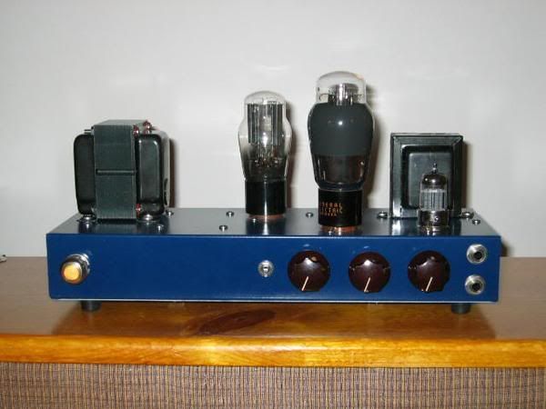
So I think the major hurdle has been cleared. Thanks again for all the help. Now the real kicker. With everything connected, I'm hitting the right voltages, but at 105 VAC!! Now I have to get a new PT with 325-0-325 instead of 350-0-350 secondary. Oh well, what's money when you're having fun. When I get a minute, I'll drop in a couple of pics so you can see what we've been discussing.

Image
Image
Image

Best, Paul
Last edited by paully on Tue Jun 17, 2008 2:41 pm, edited 1 time in total.
WADAYAKNOW.. For the first time in my life, I'm wrong again!

User avatar
mu_amps
audio school graduate
Posts: 13
Joined: Mon Mar 19, 2007 2:09 pm

Post by mu_amps » Tue Jun 17, 2008 8:11 am

paully wrote: With everything connected, I'm hitting the right voltages, but at 105 VAC
Congratulations! but why is your line voltage so low?

nclayton
steve albini likes it
Posts: 323
Joined: Sat Feb 11, 2006 8:08 am

Post by nclayton » Tue Jun 17, 2008 8:28 am

I assume you're putting in the 105 volts through a variac, right?

If so, are you measuring the AC voltage with a voltmeter, or are you reading it off of the variac's dial? Cause a lot of variacs (at least both of mine) put out your actual line voltage at the 115 volt marking, which means, since my AC line voltage is 125 volts 115=125 and 105 would probably be about 112. That would make sense, since that amp was designed back when line voltage in the US was usually 115.

Either way, I'd just plug it in to the line and see if any of the voltages go up above the cap specs. I don't think they will. You can use it with a little bit high of voltage.

If you really do want to get it down, though, there are a few ways to do it other than a new transformer. You could put something like a 100 ohm ten watt resistor in series with supply before the first cap and the plate voltage take-off point. That would drop the voltage but also SLIGHTLY alter the sound of the amp, making it sag kind of like a rectifier, since it will drop more voltage the more current comes through.

Another thing you can do is measure how much extra voltage you have, then get two 3-5 watt zener diodes of that same approximate voltage and wire them in series with the other power supply rectifier diodes, but facing the wrong way (with the cathode bands facing in towards the transformer rather than out towards the capacitor). That will drop the voltage in a pretty much constant way without sag.


Ned

User avatar
mu_amps
audio school graduate
Posts: 13
Joined: Mon Mar 19, 2007 2:09 pm

Post by mu_amps » Tue Jun 17, 2008 9:24 am

nclayton wrote:I assume you're putting in the 105 volts through a variac, right?
Ned
If you are using a variac you should also be mindful of your filament voltage. If your line was normally 117VAC and you bumped it down using a variac, unless you are running a separate filament supply, all your heaters will be under powered. What this means is that you will be applying B+ while your tubes are inadequately heated. That causes cathode stripping. The rails in your PSU will be off as well.

Your heaters are probably teetering around 5.5 volts when they should be at 6.3, or about 12% under powered.

I agree with Ned. There's no sense in going through the hassle of buying a new power transformer.

User avatar
paully
pushin' record
Posts: 223
Joined: Mon Apr 09, 2007 8:20 am
Location: Northern New Jersey

Post by paully » Tue Jun 17, 2008 3:13 pm

Thanks guys. I posted the pics above. AFA the filaments, next to the fan is a stand-alone 6.3V x 10A transformer. It's decoupled from the amps line, and I'm plugging it in directly to 117 VAC, so the heaters are seeing full voltage. BTW, that's the old Leslie 122 choke towards the rear.

After seeing the prices, I re-thought the new transformer idea. The one I'm using is not from the Magnatone. Wrong hi-sec voltage and no 50 volt sec tap for negative rail. Instead it has a 5 volt tap for the old tube rectifiers, Not sure where that thing came from :shock: :lol: ! I'm definately gonna try and use it however.

As I can re-adjust the voltages(again, trial and error) after the B+ leg, I'm gonna order some new caps for the PS with a 500 or better voltage rating and run it at 117VAC. Then if the voltages run high, which they probably will, at least I'll have some headroom. A higher value resistor before the choke will hopefully straighten the trailing rails out.

I'm using both a digital multimeter and a couple of regular old analog multimeters(backup checks) to read voltages. The 105 is correct, as I can push the right buttons and jump right from the 400 volt leg to the 117 VAC line point and check. Definately 105 with all meters. Ned, you're right about the variac's meter. It's a 5% meter, and of course it's the full 5% off. Unuseable. It reads 110 at a true 117.

I started work today on the final component; the tremolo circuit from a 50's era Fender Tremolux. The pointer on the meter waves a solid -5 to +5 variation, which should be perfect when connected to the -30 bias point. See ya'll after the smoke test :lol: .

Best, Paul
WADAYAKNOW.. For the first time in my life, I'm wrong again!

Post Reply

Who is online

Users browsing this forum: No registered users and 186 guests