oh wow, thanks for the info.
i need to read it a few times over again to take it all in.
i plan on doing all TRS connections, i have a good amount
of patch cables so i can save money by using them.
oh, how would i wire the TRS to switch?
i was just going to make some dummy plugs to do this.
but if i can wire them to switch off, it would be great.
save even some more money.
i plan on doing the panning switches so i will use the shunt resistor.
thanks again.
DIY summing mixer schematic help
I was actually just checking back over here to delete all of the messages I just wrote since it seemed like the only thing that might be of any relevance was the 232 ohm thing and you already had that. I still think you might want to still consider using 5K resistors, but probably not a big deal either way.
If you have standard 5 connection TRS jacks then all you have to do is wire the extra 2 connections (the normal-closed tip and ring switches) to each other.
Ned
If you have standard 5 connection TRS jacks then all you have to do is wire the extra 2 connections (the normal-closed tip and ring switches) to each other.
Ned
-
gabe real

- takin' a dinner break
- Posts: 160
- Joined: Tue Mar 27, 2007 2:20 pm
- Location: riverside, california
- Contact:
i think i will use the 5k resistors, so i have to use different shunt amount correct?
now on he TRS thing.
i cant find a 5 connection jack.
i thought they were just 3 pole connectors.
i was hoping to use something like these.

im gonna take a trip to the local electronics warehouse and see what they have.
now on he TRS thing.
i cant find a 5 connection jack.
i thought they were just 3 pole connectors.
i was hoping to use something like these.
im gonna take a trip to the local electronics warehouse and see what they have.
-
gabe real
- takin' a dinner break
- Posts: 160
- Joined: Tue Mar 27, 2007 2:20 pm
- Location: riverside, california
- Contact:
ok, im changing my design, no more pan switches. it will cost too
much and be a pain to do for all 14 inputs.
the 4P3T toggles are about $11 each from mouser.
so im just gonna make it with more channels. i will use the 5 pin TRS
jacks and switch the contacts for a off. i found some jacks at the electronics store.
i figured this part out. pretty easy.
so i will do 8 stereo and 8 mono. so 24 jacks all together.
the jacks are $2.60 each. so $62 just for the jacks.
plus 2 more jacks for outputs.
so $67.60 for the jacks.
about $10 for resistors
about $30 for a chassis(non rackmount)
so, the other option is a patch bay.
do i need any special one to do this.
could i use a Neutrik NYS-SPP-L.
http://www.neutrik.com/fl/en/audio/210_ ... etail.aspx
thanks again
-
gabe real
- takin' a dinner break
- Posts: 160
- Joined: Tue Mar 27, 2007 2:20 pm
- Location: riverside, california
- Contact:
new math and schematic
10K/24)200 / (10K/24) - 200
10k divided by 24 = 416.7
416.7 x 200 = 83333.3
83333.3 divided by 216.7 = 384.6
so a 385 shunt on outputs?
i changed the resistors to 5k so then it would change the equation correct?
i changed the 20k to 10k because i thought-
2 x 10 = 20
2 x 5 = 10
i hope this is right.
so a total of 24 channels-
8 center or mono
8 pan left
8 pan right
this is just a short version of full schematic
i need to connect the grounds together, than to chassis also.
-
The Scum
- mixes from purgatory
- Posts: 2750
- Joined: Thu Jul 03, 2003 11:26 pm
- Location: Denver, CO
- Contact:
A couple things:
I've never actually met a 4-pole, 3 throw toggle switch...do they even exist?
NYDave intended for it to be a rotary switch - $2.20 fron Mouser.
If you use mute switches as shown, you don't need to use the shorting sockets, either.
Also, your use of 24 in the math isn't correct: there are indeed 24 jacks, but only 16 on the left buss, and 16 on the right buss. Each buss gets the 8 mono/center channels, and the 8 that feed only it. The other 8 can be ignored.
Your schematic is also incorrect: you calculated a 385 Ohm resistor, but listed a 385K.
-
gabe real
- takin' a dinner break
- Posts: 160
- Joined: Tue Mar 27, 2007 2:20 pm
- Location: riverside, california
- Contact:
yup, i put the k after the 385, that was a mistake.
well, if i dont use the mutes or the panning, wiring is
much easier, plus i get more channels.
might even be cheaper.
but if they have rotary 4p3t, it might be possible.
i think i will go with the switched TRS jacks,
it will eliminate the need for the mutes.
10K/16)200 / (10K/16) - 200
10,000 divided by 16 = 625
625 x 200 = 125,000
125,000 divided by 425 = 294
294 ohm shunt.
so i was right with changing the 20k to 10k?
i was also considering a case from here-
http://www.par-metal.com/
Although in theory I agree with the reasons for using 5K resistors, apparently the reason NYDave recommends 10K is that he has found that they provide the optimal crosstalk to gain loss ratio. Also, trying to find a line amp that's going give you 23db of gain is not nearly as easy as plugging right into a pair of preamps that you already own (we love multitaskers). Either way, it'll work. I find the noise with the 10K resistors to be nominal.
The other benefit is that you can taylor your mix color by what preamps you choose rather than committing to a dedicated line amp. When I'm doing a clean pop record, I use my SSL pres. When I'm doing a rock record, I use my vintage RCA germanium pres. Etc...
Opinions are like a-holes. That's mine. Good luck with your build.
-
gabe real
- takin' a dinner break
- Posts: 160
- Joined: Tue Mar 27, 2007 2:20 pm
- Location: riverside, california
- Contact:
thanks for the reply.
my goal was to use different preamps too.
i can still use one to add the 23db of makeup gain.
i just wont have to drive it as hard.
but, in driving a preamp hard, the sound changes and you get a different tone.
so, i may go back to the 10k resistors.
i would rather have to turn the gain up, then barely even
use make up gain at all. i have a altec preamp thats
really hot, i need to build db pads. i almost get distortion from a beyer m201
and senn md421 at the lowest input gain.
so, the higher ohm load would be better in the long run.
i plan on getting different preamps to drive this thing.
plus those same preamps will be used for mics too.
if i dont like it, i will change it.
we are only talking a few dollars here, if that.
if its not completely correct, i dont think i will blow anything up.
new math-
(20K/16)200 / (20K/16) - 200
20,000 divide by 16 = 1250
1250 x 200 = 250,000
250,000 divided by 1050 = 238
238 ohm shunt
-
gabe real
- takin' a dinner break
- Posts: 160
- Joined: Tue Mar 27, 2007 2:20 pm
- Location: riverside, california
- Contact:
well, i successfully built a box.
its 4 stereo channels (4 left and 4 right)
then i made 2 with pan toggles
(so when its up its center, when down its left, or right depending on channel)
i did this with a 3pdt toggle. ( one input and 2 selectable outputs)
so the middle 2 poles were the input from TRS jack,
the top to poles were for left out.
then the bottom 2 poles were for mono or center.
this works because i put the mono split wires with resistors
off the output of the toggle.
so the top poles just had one 10k resistor per pole.
the bottom had two 14.3k resistors per pole.
i tested it out and it works
then i had 2 more channels just mono or centered.
so i can have 4 stereo and 4 mono
or i can have 6 stereo and 2 mono.
i ran out of space in the small case i used so its a small
channel count.
i will post pictures later tonight. its pretty
much just resistors and solder with only a few small pieces of wire.
looks like a mess, but an organized one. reminds me of
some old point to point electronics or something.
it was made from a gutted patch bay i bought on ebay,
i didnt know it was RCA on the back so i just used the case for
this project, it was only $30, no big deal.
pics will be up tonight
It sounds like you've got something working, so probably you don't need any more input, but I thought I'd just mention a couple of things.
Since you've got the shunt resistor you've probably already found out you need more than 23dB gain, probably something more like 30dB at least, I can't remember how many channels you said you did. The 23dB was what you'd need if you didn't need a shunt resistor and went with more like a 600 ohm output. Whatever.....
As long as all the inputs are fairly accurately balanced, you shouldn't have too much crosstalk in your mixer. But if you want to really get rid of the crosstalk you might want to also ground the switching connection on the centered input jacks. That way when nothing's plugged into them, there's no way for signals to get from one channel to the other. The way it is right now, theoretically there shouldn't be any signal at that point since the 2 out of phase signals should totally cancel, but in real life that depends on really perfect balancing and really perfect resistor matching, which of course doesn't quite happen. You probably don't need to worry about this creating any grounding issues since the grounds will all be isolated from the lines by the 9.3k resistors.
Ned

-
gabe real
- takin' a dinner break
- Posts: 160
- Joined: Tue Mar 27, 2007 2:20 pm
- Location: riverside, california
- Contact:
well, it works good. i used a sytek for make up gain,
turned the gain on the sytek to about 3 or so.
any higher and i would get a peak light on
the aurora 16. so maybe 15 to 25 db for make up gain here.
it has more separation than the ITB mixes i have done.
i might do a little clean up job on this project, its
kind of a mess.
more info later, its been a long weekend.
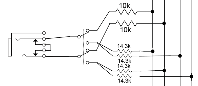
here is the schematic for the switched channels.
now that i look at it, i dont know if the toggles i got will
terminate the signal to the opposite poles.
this might create a problem, it sounded ok when
i tested it.
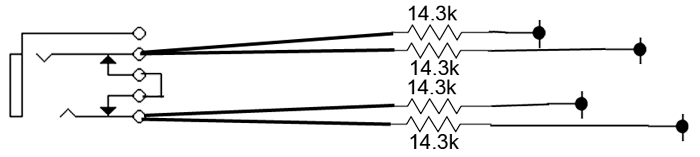
here is the schematic for the left or right panned channels-
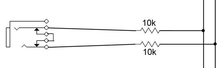
here is the mono channel-
and here is the full schematic-
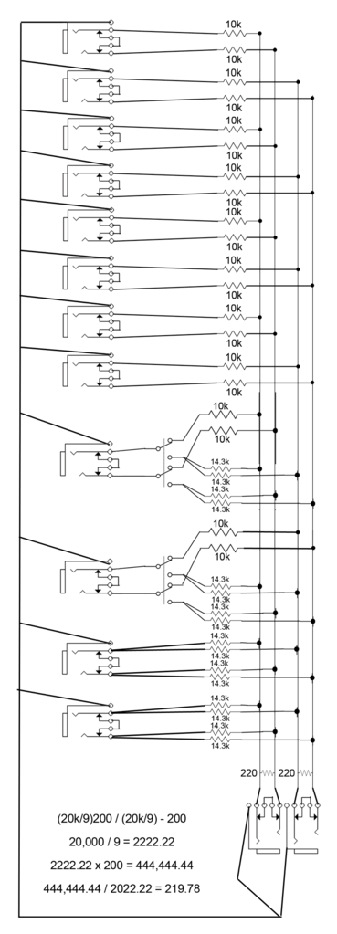
i think it should of been 8 channels, i just counted how many times each buss had something connected to it, so that would be 9
math for 8 channels-
(20K/8)200 / (20K/ 8 )-200
20,000 / 8 = 2500
2500 x 200 = 500,000
500, 000 / 2300 = 217 shunt
so, i think 220 shunt is close enough here.
after all, its just a little bit more make up gain, right?
thanks for the input people, i really appreciate it!
thanks!
turned the gain on the sytek to about 3 or so.
any higher and i would get a peak light on
the aurora 16. so maybe 15 to 25 db for make up gain here.
it has more separation than the ITB mixes i have done.
i might do a little clean up job on this project, its
kind of a mess.
more info later, its been a long weekend.
here is the schematic for the switched channels.
now that i look at it, i dont know if the toggles i got will
terminate the signal to the opposite poles.
this might create a problem, it sounded ok when
i tested it.
here is the schematic for the left or right panned channels-
here is the mono channel-
and here is the full schematic-
i think it should of been 8 channels, i just counted how many times each buss had something connected to it, so that would be 9
math for 8 channels-
(20K/8)200 / (20K/ 8 )-200
20,000 / 8 = 2500
2500 x 200 = 500,000
500, 000 / 2300 = 217 shunt
so, i think 220 shunt is close enough here.
after all, its just a little bit more make up gain, right?
thanks for the input people, i really appreciate it!
thanks!
-
thesimulacre

- takin' a dinner break
- Posts: 171
- Joined: Tue Dec 20, 2005 10:26 pm
- Location: Colorado
So I just picked up a crap-ton of resistors, and it seemed to really have put a hurt on the guy at Fistel's electronic cavern... so I really don't want to return them if I don't need to but here's the thing. They are all 1/4W. All of the other designs I have seen have what look like at least 1/2W resistors and I do not know how to figure the current from the outputs of my interface (especially since I just sold it  ).
).
I seem to remember that a full-scale +4 signal is up around 25V but without knowing the current that number is kinda meaningless. I would hate to wire up 64 of these things (16channel) and find out I have to return them. At least they are 1% so I figured I could get away with 5K all around.
Any thoughts? Not trying to hijack, just to keep related info in the same topic, as these threads have been notoriously hard to track down.
Who is online
Users browsing this forum: No registered users and 43 guests