I have completed first half of 1678 modding:re-direct the linear output through volume pot.
HPF also works!
I still wait potentiometers for gain and preparing for them a place have taken out LED's
Amateurish question:
Whether I can them to cut off from a board or should leave for the further functioning?
If it is interesting I can lay out pictures of my work,but they completely repeat the way described here
altec 1678c mod..direct out/gain control..AUDIO SAMPLES!

-
RodC

- dead but not forgotten
- Posts: 2039
- Joined: Thu Dec 30, 2004 8:53 pm
- Location: Right outside the door
- Contact:
You can cut them out our leave them, it should not affect the audio path.vowan wrote:I have completed first half of 1678 modding:re-direct the linear output through volume pot.
HPF also works!
I still wait potentiometers for gain and preparing for them a place have taken out LED's
Amateurish question:
Whether I can them to cut off from a board or should leave for the further functioning?
If it is interesting I can lay out pictures of my work,but they completely repeat the way described here
'Well, I've been to one world fair, a picnic, and a rodeo, and that's the stupidest thing I ever heard come over a set of earphones'
http://www.beyondsanityproductions.com
http://www.myspace.com/beyondsanity
http://www.beyondsanityproductions.com
http://www.myspace.com/beyondsanity
-
stupid_life
- ass engineer
- Posts: 45
- Joined: Thu Jul 01, 2010 12:04 am
I originally thought I had a power supply issue with my 1606b which is one of the octal based altec mixers, but I tested it and it's working fine, it's just that the bulb inside of the power switch is burnt out. Does anyone know of a type of bulb I could use for a replacement to go inside of this switch? Could I use an LED or should I not, since it is a Diode?
-
apropos of nothing

- dead but not forgotten
- Posts: 2193
- Joined: Tue May 13, 2003 6:29 am
- Location: Minneapolis, MN
- Contact:
-
vowan

- audio school graduate
- Posts: 12
- Joined: Tue Jun 30, 2009 3:01 pm
- Location: Saint Petersburg,ru
- Contact:
inline pad
I have -20 dB inline pads.
I can manipulate between them and pad switch on rear panel depending from source's level.
I can manipulate between them and pad switch on rear panel depending from source's level.
-
vowan
- audio school graduate
- Posts: 12
- Joined: Tue Jun 30, 2009 3:01 pm
- Location: Saint Petersburg,ru
- Contact:
altec 1678 mod
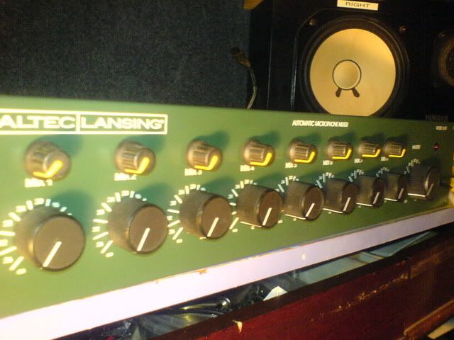
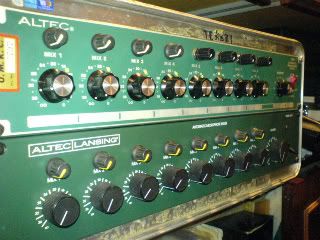
I finish my mod of 1678 and now it's look like this:
Wire mounting is the same as describe here.
I put 1k pots for gain control but that's not enough to reduce gain with high SPL source(close drums).
I was trying 5k and find those more usable.
But not sure about permissible for circuit.
Anyway now i have more 8 mic pres in addition to my DAW.
Thanx for everyone here.
Vladimir
-
djboomstick
- audio school
- Posts: 2
- Joined: Thu May 26, 2011 6:52 pm
- Location: upstate ny
altec 1678
vowan that minty green one looks great!!!
if i find a green one i'm gonna have to get it.
i just finished with a 1678b
i decided i like LEDs too much to take them out so i kept them and tapped and drilled new holes.
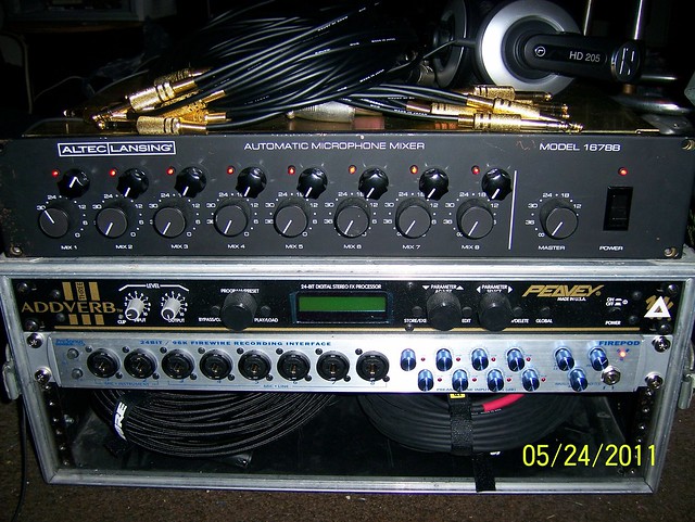
the pile of cables with gold ends are wired tip-sleeve-no ring for use with the 1678.
i don't really understand the how the logic control in the ring is meant to work with the 1678 but making it work like this and doing the mods was really a lot of fun.
none of my work would have been possible with out this board. so, thanks to everyone that did the hard work in figuring this out and making it easy for me.
THANKS !
i have questions about the output knob mod.
i really don't know alot about electronics so i decided to just tap off the resistor, and not actually remove the resistor.
i just added a wire running from the resistor to the knob. mainly i was testing things out to see if i could get it to work at all before actually cutting parts out.
my question is ; is this bad for any reason? am i making a mess of the circuit this way ? and , will this unit still function as a mixer if these resistors are removed ?
the only thing in testing was the curve of the output was not smooth across the full range of motion of the output control. not really silent all the way down and only a slight increase in level across the first 70% of the range and most of the action in the last 30% of the range.
my thought is it might be smoother across the range and have zero output when set all the way down with out the resistor.
i don't have another unit to compare to maybe its like this anyways even with the resistor removed??
i'm willing to live with this unsmooth action as a compromise to keeping the mixer function if its otherwise not a bad idea. i don't wanan burn some part of it out.
one of the reasons i liked this unit was because its a mixer AND has all the direct outs. if its not good for the components to work this way i may have to undo the output mod to keep mixer function.
i hope some one with more knowledge than me can make some sense of what i'm asking and offer some advice
thanks again to every one who posted before you've been very inspirational!
if i find a green one i'm gonna have to get it.
i just finished with a 1678b
i decided i like LEDs too much to take them out so i kept them and tapped and drilled new holes.
the pile of cables with gold ends are wired tip-sleeve-no ring for use with the 1678.
i don't really understand the how the logic control in the ring is meant to work with the 1678 but making it work like this and doing the mods was really a lot of fun.
none of my work would have been possible with out this board. so, thanks to everyone that did the hard work in figuring this out and making it easy for me.
THANKS !
i have questions about the output knob mod.
i really don't know alot about electronics so i decided to just tap off the resistor, and not actually remove the resistor.
i just added a wire running from the resistor to the knob. mainly i was testing things out to see if i could get it to work at all before actually cutting parts out.
my question is ; is this bad for any reason? am i making a mess of the circuit this way ? and , will this unit still function as a mixer if these resistors are removed ?
the only thing in testing was the curve of the output was not smooth across the full range of motion of the output control. not really silent all the way down and only a slight increase in level across the first 70% of the range and most of the action in the last 30% of the range.
my thought is it might be smoother across the range and have zero output when set all the way down with out the resistor.
i don't have another unit to compare to maybe its like this anyways even with the resistor removed??
i'm willing to live with this unsmooth action as a compromise to keeping the mixer function if its otherwise not a bad idea. i don't wanan burn some part of it out.
one of the reasons i liked this unit was because its a mixer AND has all the direct outs. if its not good for the components to work this way i may have to undo the output mod to keep mixer function.
i hope some one with more knowledge than me can make some sense of what i'm asking and offer some advice
thanks again to every one who posted before you've been very inspirational!
-
vowan
- audio school graduate
- Posts: 12
- Joined: Tue Jun 30, 2009 3:01 pm
- Location: Saint Petersburg,ru
- Contact:
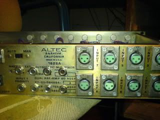
I have at last finished 1628 mod.
My device had a problem with the power unit: at first has changed MC1468L - ADJUSTABLE POSITIVE VOLTAGE REGULATOR - wasn't +15v. To find him now is not simple - the order long waited.
Also has changed capacitors, but the problem was not in them.
Eventually malfunction of the diode bridge was found out - gave out not equal values.
After his replacement have disappeared all hums and pressure was normalized.
Further has made re-capping in some 1588с modules.
Problem that there inside axial capacitors of very small size and them too difficult for finding. Otherwise not probably to insert all back.
In the rest all is made under project RodC for what to him many thanks!!!
All good luck!
-
RodC
- dead but not forgotten
- Posts: 2039
- Joined: Thu Dec 30, 2004 8:53 pm
- Location: Right outside the door
- Contact:
Hey Vowan, your 1628a looks nice. I havent used and of the 1588c models that have the electrolytic caps yet, all of mine have the small ceramic and tantalum caps. I think the Vishay Littl-lytic series will fit, they are a bit bigger, but I think they will fit:vowan wrote:Further has made re-capping in some 1588с modules.
Problem that there inside axial capacitors of very small size and them too difficult for finding. Otherwise not probably to insert all back.
(Mouser sells them)
http://www.mouser.com/catalog/specsheets/tvaatom.pdf
http://www.mouser.com/ProductDetail/Vis ... CqmK0dw%3d
http://www.mouser.com/ProductDetail/Vis ... 78gfe4M%3d
http://www.mouser.com/ProductDetail/Vis ... 68nXsbw%3d
For a size ref you can see my pics with measurements here:
http://beyondsanityproductions.com/inde ... &Itemid=28
'Well, I've been to one world fair, a picnic, and a rodeo, and that's the stupidest thing I ever heard come over a set of earphones'
http://www.beyondsanityproductions.com
http://www.myspace.com/beyondsanity
http://www.beyondsanityproductions.com
http://www.myspace.com/beyondsanity
-
vowan
- audio school graduate
- Posts: 12
- Joined: Tue Jun 30, 2009 3:01 pm
- Location: Saint Petersburg,ru
- Contact:
1588c recapping
Hey RodC.
Thanx for links for capacitors.
Fortunately not all capacitors should be changed.
The greatest problem with the cap(10uf) which is more close to transistor package - it rests against that. But I interchanged the position of them(10uf caps) and while all OK.
Also I managed to find some nominals 4мм in diameter.
The main problem that in russia isn't present good components available and it is necessary to wait long the order and to overpay.
For one MC1468L have asked 300$!!!
While in Finland to me it was possible to buy for 1,5$
On queue 4 piece of amek2000m modules from which I want to construct four channel preamplifier. But it is a subject of other post.
-
RodC
- dead but not forgotten
- Posts: 2039
- Joined: Thu Dec 30, 2004 8:53 pm
- Location: Right outside the door
- Contact:
I understand vowan. I have a couple of other contacts in Russia. If you get in a pinch let me know and I can mail you some. The postage is expensive and slow, but sometimes its cheaper and we can trade.
'Well, I've been to one world fair, a picnic, and a rodeo, and that's the stupidest thing I ever heard come over a set of earphones'
http://www.beyondsanityproductions.com
http://www.myspace.com/beyondsanity
http://www.beyondsanityproductions.com
http://www.myspace.com/beyondsanity
Hello Jim, I'm modding a 1678c right now and I'd like to know what would be the advantages of using some other opamps, I'm from Argentina and I have access to OP07CP, OP177GP, OP27GP and LF353. Are these any good?Jim Williams wrote:Now try some audio mods. Replace that 5534 and it's leaf socket. Use a Millimax or similar machined socket. Add a pair of .1 uf mono ceramic caps from pin's 4 and 7 to ground on each 5534.
Try these superior opamps: LME49710NA, LME49990, OPA1610, LT1357CN, AD8597, ADA 4898-1, ADA 4627-1. These are precision opamps with very low DC offsets. With the AD parts you can short out the gain set coupling cap for direct coupled sonics. Some are SOIC only, use Brown Dog or Aries adaptors to mount surface mount parts.
Thanks in advance, I'll post pics when I'm done with the mods.
-
okcrecording
- gimme a little kick & snare
- Posts: 98
- Joined: Wed May 05, 2004 3:05 pm
- Location: OK
Rise thred, RISE!!!
I realize this thread is rather old, but I had a few questions for the authors. I acquired an Altec 1678c in excellent condition and have started the mod. I wanted to take things a bit further and add some extra functionality. I mounted SPDT switches to the front panel along with the input gain potentiometers mentioned in the previous posts. The intent was to make the high pass filter switchable, but two problems reared their head in the process. The first problem is that when the high pass filters are switched into the signal path, there is a slight, but noticeable distortion in the signal that is not there when it is switched out. The second problem is the HPF frequency. Obviously its too high at its stock value, but looking at the schematic it appears that R105 (R305 in the schematic) is the output potentiometer and the frequency is calculated using R105 and C108. My question is, how can I lower the frequency to ~80hz , my assumption would be change either R105 or C108, but I'm certain changing the value of R105 would also affect the rest of the circuit.
Any help in this matter would be appreciated. Thank you in advance.
Any help in this matter would be appreciated. Thank you in advance.
Hey guys,
This is some great info. I just ordered a 1678C and can?t wait to try it out. I have a couple of questions though. According to the schematic, the 560 ohm resistor reduces the gain by 14db. and after you installed a 1K pot in it?s place the signal was still too hot for most applications and needed an in-line pad to control. Is there a good solution for adding a switchable pad into this path? This may be an ignorant guess but if a 560 ohm resistor reduces the signal by 14db then the 1K pot should be the equivalent of a variable 25db pad. If you are still needing an in-line 20db pad then wouldn?t a on/off switchable 800 ohm resistor to ground do the same thing?
Next, the phantom power is from what I?ve read mostly unusable at only 18V. Would it be possible to add a small step-up transformer in the power section that takes the +18V rail and makes it +48V. Would this affect the transistor(Q301) on the input transformer? Does it need to be changed out for the increased voltage?
The manual states that this unit has 90db of gain with the pad disengaged. How much of this is due to the output transformer and has anyone left one of the channels running through the output transformer to see what a difference it makes to the sound of the unit. I?m guessing the auto level control section on the PCB would not get used at all and could probably be removed all together. If you wanted to add an output transformer to each channel this seems like it would be a good place to mount it. Any thoughts?
Lastly, how would you make the outputs balanced and do you think it would be worth it?
Who is online
Users browsing this forum: No registered users and 204 guests