DIY Reamp
-
GravityRobert

- ass engineer
- Posts: 41
- Joined: Mon Apr 09, 2007 9:26 am
-
GravityRobert
- ass engineer
- Posts: 41
- Joined: Mon Apr 09, 2007 9:26 am
I got my parts from mouser, now waiting on casing and traffies.
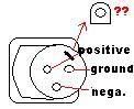
Anyway, I got this one part I'm not sure about how to mount it ie whether I need to drill aditional holes. Both of my switches have these washers with a edge to them as seen here
Does that mean I have to drill another small hole in the box for it? -Like with the potmeter's keepers?
Heres the order on which its screwed on:
nut - teethed washer/grip washer - washer with edge ^^ - nut
I assume I should mount them like this
nut - teethed washer/grip washer - washer with edge ^^ - Casing - nut
You are correct, Robert. That little washer deal is a sort of keeper like the ones that are fixed on VR1 and VR2. I use such things for pots, since I don't like having the pot loosen and rotate in the mounting holes. You'll notice that I did specify keeper holes for the pots but not the switches. For switches I think the keepers are darn near useless, and I toss them...
I thought this club was for musicians. Who let the drummer in here??
-
GravityRobert
- ass engineer
- Posts: 41
- Joined: Mon Apr 09, 2007 9:26 am

-
GravityRobert
- ass engineer
- Posts: 41
- Joined: Mon Apr 09, 2007 9:26 am
Hello, if any of you gentlemen would be so kind to check if my wiring I did today is ok. I havent received my transformators just yet (damn you UPS, last time I'll use their service, it should be overnight shipping and they're late, they're due next week...) so that's all theres left to do, rest of the wiring should be done. I've also used heat shrinking tubing to cover up the resistor, I'm not sure if that's a good idea or anything but I enjoyed working with that fabric so much and I inhaled too much of the plastic fumes 
Here's the link, I hope the pictures speak for themselves
http://s135.photobucket.com/albums/q130 ... %20wiring/
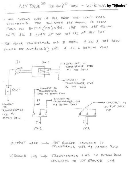
and here's the schematic:
http://i135.photobucket.com/albums/q130 ... /page4.jpg
Here's the link, I hope the pictures speak for themselves
http://s135.photobucket.com/albums/q130 ... %20wiring/
and here's the schematic:
http://i135.photobucket.com/albums/q130 ... /page4.jpg
-
GravityRobert
- ass engineer
- Posts: 41
- Joined: Mon Apr 09, 2007 9:26 am
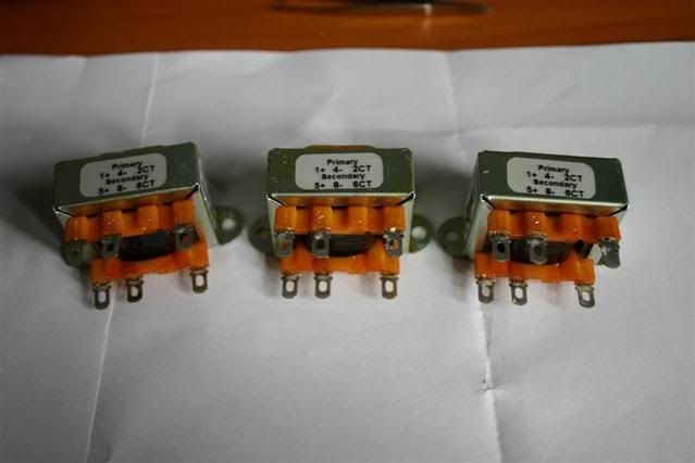
Yeah...more little details I've clearly missed. Sorry. The way I wrote those directions, the top row stabs marked 1 -4 (even though #3 is clearly missing) correspond to what I have written; meaning if I wrote "top row stab #4" then connect to the top row stab marked "4". Bottom row stab #1 would be the one marked on the transformer as "5" (the first stab on the bottom row) and bottom row stab #4 would be the one marked "8" (the 4th stab on the bottom row).
These little details and some of the confusion around them are one of the reason schematics were developed in the first place. Take the text out of the picture. Putting the text back into the picture can be a way of complicating things, but sometimes it's the only way to get an idea across to those that can't read the schematics...
These little details and some of the confusion around them are one of the reason schematics were developed in the first place. Take the text out of the picture. Putting the text back into the picture can be a way of complicating things, but sometimes it's the only way to get an idea across to those that can't read the schematics...
I thought this club was for musicians. Who let the drummer in here??
-
GravityRobert
- ass engineer
- Posts: 41
- Joined: Mon Apr 09, 2007 9:26 am

Who is online
Users browsing this forum: No registered users and 203 guests