
The output of my mixer runs a little hot for my interface, and I want to build a pad to drop around 6dB.
Do I have to pad both pins as it's a balanced line?
Padding an XLR cable
Padding an XLR cable
The previous statement is from a guy who records his own, and other projects for fun. No money is made.
Re: Padding an XLR cable
Yep, else you'll compromise your CMRR (noise rejection). You only need 3 resistors, though. One in series with each of "hot" and "cold" (matched as closely as possible, sometimes you can get closer by paralleling a couple resistors), and one between the two. No need to hit "ground" with this pad at all.Drone wrote:The output of my mixer runs a little hot for my interface, and I want to build a pad to drop around 6dB.
Do I have to pad both pins as it's a balanced line?

Resistor values should be scaled for the expected source and load.
That'll probably work fine, except that it's going to give you more like 10db. You said you wanted 6, which would indicate something like 1K for the R1s and 2K for R2. But...
...There are other impedances in play that are not really depicted on that diagram. Both the source and load will have an effect, and with some line level gear, their values are close enough to make a real difference in the calcuations. If "about 6db" is what you're shooting for, and you're not too worried if it ends up being 7 or 8db instead, that's cool. If you really want to know what you're doing to the signal, then you need to figure out the voltage divider ratio of the system as a whole.
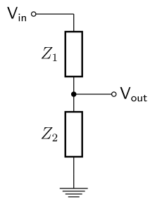
Divider Ratio = Z2 / (Z1 + Z2)
In this case
Z1 = 2 * R1 + SourceZ
Z2 = R2 || LoadZ = (R2 * LoadZ) / (R2 + LoadZ)
It's not really difficult math as long as you know the numbers. If you happen to have 1K impedance at the source(not completely unheard of, and pretty close to 600Ohm "standard"), and 10K at the load (maybe a little low nowadays, but not terribly uncommon), and the numbers I suggested above, your divider ratio ends up 0.357, which is almost 9db! Your 1K and 1K would give -12db.
If you really want precision, you'll have to find the numbers for the gear you're using and work it out. Probably just pick a reasonable value for one of the Rs, then work out what the other has to be for your system. Ideally, you would specify your Rs based on the value of the coupling capacitor on the board's output and the maximum current drive of the amplifier before it, but...
I think if you stuck 1K in the R1s and then strap a 20K pot as a variable resistor for R2, you could either just leave it as a variable attenuator, or dial it in to what you want, measure it's value, and replace it with an static R.
...There are other impedances in play that are not really depicted on that diagram. Both the source and load will have an effect, and with some line level gear, their values are close enough to make a real difference in the calcuations. If "about 6db" is what you're shooting for, and you're not too worried if it ends up being 7 or 8db instead, that's cool. If you really want to know what you're doing to the signal, then you need to figure out the voltage divider ratio of the system as a whole.
Divider Ratio = Z2 / (Z1 + Z2)
In this case
Z1 = 2 * R1 + SourceZ
Z2 = R2 || LoadZ = (R2 * LoadZ) / (R2 + LoadZ)
It's not really difficult math as long as you know the numbers. If you happen to have 1K impedance at the source(not completely unheard of, and pretty close to 600Ohm "standard"), and 10K at the load (maybe a little low nowadays, but not terribly uncommon), and the numbers I suggested above, your divider ratio ends up 0.357, which is almost 9db! Your 1K and 1K would give -12db.
If you really want precision, you'll have to find the numbers for the gear you're using and work it out. Probably just pick a reasonable value for one of the Rs, then work out what the other has to be for your system. Ideally, you would specify your Rs based on the value of the coupling capacitor on the board's output and the maximum current drive of the amplifier before it, but...
I think if you stuck 1K in the R1s and then strap a 20K pot as a variable resistor for R2, you could either just leave it as a variable attenuator, or dial it in to what you want, measure it's value, and replace it with an static R.
Close enough is close enough! 2 x 1K in series = ...
TBH, you could probably lose 6db just by running an unbalanced line. Heresy, I know. If it ends up noisier, you could try pseudo-balanced. It might be quieter, and you'll still lose that half of the signal.
But this kind of begs the question: Are you sure you're not just running the mixer too hot? Is there some magic that happens when you slam the board? Does turning it down make a noticeable difference in your S/N ratio? What mixer and what interface are we talking about?
Yes I am running the mixer too hot, and yes there is a magic that happens 
The mixer is my instrument preamp, I use it to drive a couple of tube amps, heresy I know. I drive the amps from the 1/4" unbalanced outs of the submix, which is fed from the master buss, and I use the balanced XLR outs of the master buss as DI into my interface a Delta 1010LT which just happens to have two XLR inputs.
This way I can use the submix faders to adjust the levels to the amps and I can keep the master buss slammed gently, which is where it sounds best.
I suppose if cutting the signal to unbalanced would help, I can use a pair of XLR to RCA jacks and feed a pair of the unbalanced inputs instead with the output of the mixer, and then feed the XLR inputs with the outputs from my recording mixer. That just means using a few more adaptors again.
The previous statement is from a guy who records his own, and other projects for fun. No money is made.
It's worth a shot. I worry, though, when you mention RCA, because that almost always means nominal -10dbV, which is basically about 12db more sensitive than a the (probable) +4dbu that the XLRs "expect". So, you'll drop 6db going to unbalanced, but you'll still hit the DAW 6db louder than before! (Pleade realize I'm not actually familiar with your interface, just kind of educated-guessing)Drone wrote:I suppose if cutting the signal to unbalanced would help, I can use a pair of XLR to RCA jacks and feed a pair of the unbalanced inputs instead with the output of the mixer, and then feed the XLR inputs with the outputs from my recording mixer. That just means using a few more adaptors again.
What you could do is short the - and ground pins on the XLR cable together. For some gear, you'd want to do this on the input end and leave one of them N/C on the output end, but for most modern stuff you can just jumper at one end and be fine. Probably not a great idea where there's phantom power involved...
Who is online
Users browsing this forum: No registered users and 356 guests