Using the archived copy of the article here: http://recordinghacks.com/articles/how- ... icrophone/
(If this has been covered elsewhere, please let me know---I didn't find anything directly in the archives but my search fu may of course be weak.)
I'm considering building a couple of these to experiment with as boundary mics in places I don't want anything expensive---e.g., taped to the floor of a stage in a rock club. My thinking is that the cap can sit at the end of a ~6ft cable to the power box (just enough to keep the power box out of harm's way) and then run an XLR to wherever from there.
I was thinking a transformer in the power box might be nice to (a) protect the capsule from phantom, (b) balance the output, (c) attenuate the signal and (d) drop the impedance for a normal mic input. Obviously, I'm not looking at anything expensive. But for $13 per, I was wondering if this little guy might work:
https://www.edcorusa.com/xsm10k-600
(This is a 4.1:1 transformer. Assuming the electret has an output impedance of 2K2, this should yield 2K2 / (4.1^2) = ~130 ohms, which should be good.)
Does this seem like a reasonable plan? Thoughts? Thanks.
adding xfmr to diy/tapeop omnis

I think a second Mylar cap on the pin 3 line would be all you need to protect against phantom power disasters. As to the rest, they don't run that hot in my limited experience, and they are balanced.
The previous statement is from a guy who records his own, and other projects for fun. No money is made.
-
Scodiddly

- genitals didn't survive the freeze
- Posts: 3979
- Joined: Wed Dec 10, 2003 6:38 am
- Location: Mundelein, IL, USA
- Contact:
If you're getting to that point, you might as well just shift to building phantom-powered mics instead of buying transformers. The next step in the circuit is the classic "PZM phantom power" circuit, or one of the many other variations on an old Shoeps circuit.
Here's my version for Panasonic and similar capsules:
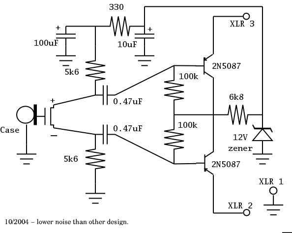
Here's my version for Panasonic and similar capsules:
Yeah, I thought about phantom power, and looked at that circuit. I guess I have it in my head that 9VDC from a battery will be both cleaner and more reliable in terms of providing a constant voltage---usually I'll have a nice preamp handy, but if not, e.g. I remember not wanting to phantom power anything with my Zoom handheld. Does that seem like a reasonable concern, or am I overthinking this?
(I work with computers in the daytime, and there's slogan: "Premature optimization is the root of all evil.")
Anyway, if I was using a battery anyway (instead of PP) wiring up a transformer seems pretty easy. If PP is the best option for powering the mic, then you're probably right, the circuit below would be the way to go.
The thing being transformers and phantom power go hand in hand. The idea is instead of using a bunch of components, you use a transformer to get the supply voltage and isolate the audio from DC, I imagine you could redesign the original circuit to not require a cap, and just use a battery, but then you need two transformers, one at each end.
Here you could just have a regulator on the centre tap.
Here you could just have a regulator on the centre tap.
The previous statement is from a guy who records his own, and other projects for fun. No money is made.
-
Scodiddly
- genitals didn't survive the freeze
- Posts: 3979
- Joined: Wed Dec 10, 2003 6:38 am
- Location: Mundelein, IL, USA
- Contact:
The center-tap thing for phantom is no longer in style. You really don't want DC current flowing through a transformer if you can find some other way. The current style is just to use 6k8 ohm resisters from the 48v supply to each of pins 2 and 3... that's actually the spec, and limits the current appropriately.
Who is online
Users browsing this forum: No registered users and 77 guests