if you want low distortion and low noise, go with the THAT chips. if you want euphonic distortion, something like what i posted above or a tube pre would make sense. tube power supplies are more difficult and dangerous to build, and tubes will drive the cost up considerably. you can make a nice sounding preamp with fets; there's nothing magical about tubes...
the edcor input xfmr i used was a 1:5.
Simple scalable mic preamp

Are you meaning just from the HV concerns? Or keeping the heater noise down low enough?
Did you work from a schematic or application note for the FET design?
I think the thing I like about tubes, is that they are expensive enough that they keep the parts count down. When transistors came on the scene, it wasn't enough to just have a gain stage, suddenly we were using extra buffering stablizing, etc. What was done with a single tube stage suddenly took half a dozen transistors.
I had to look up what Euphonic meant
The previous statement is from a guy who records his own, and other projects for fun. No money is made.
mostly the HV. if you're set on tubes, you might look up new york dave's one bottle preamp over on groupdiy. simple and well documented.
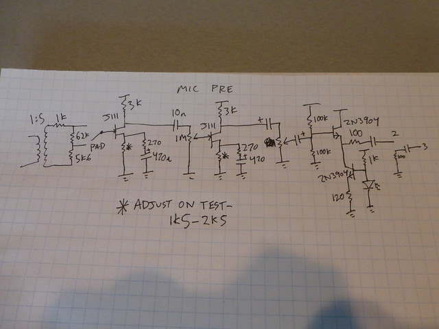
i'd be happy to post a schematic for mine if you want; there's not much to it.
you could look at it the other way: transistors are cheap enough that they allow one to do things right, even if it takes half a dozen of them...simplicity doesn't always lead to best performance, and one can buy quite a few transistors for the price of a tube or transformer.
True, but the time taken to hardwire a bunch of transistors can be annoying, and the time taken to fault find a circuit, also annoying, not that I'm anti transistor.
If you have a schematic for yours, I'd be curious, are those bits of opto-electronics in the box as well?
I will check out the one bottle preamp too, thanks http://wiki.diyrecordingequipment.com/p ... le-preamp/
Fear not, I'm a certified (at least my wife thinks I'm certifiable) tech, HV is not a problem
The previous statement is from a guy who records his own, and other projects for fun. No money is made.
-
The Scum
- moves faders with mind
- Posts: 2746
- Joined: Thu Jul 03, 2003 11:26 pm
- Location: Denver, CO
- Contact:
If cost is a concern, opamps (or the THAT chip pres) are probably the best bang for the buck.
Unless you've got parts to scavenge, a modest HV power supply probably runs $50 in parts...$35 transformer, a couple of $5 400V caps, etc. Most tube mic pres need input transformers, and you'll probably want to use tube sockets, which again don't come cheap.
Transistor/JFET circuits are a good learning experience, but the external components start to add up...extra caps for AC coupling in and out, setting AC bias points, etc.
That said, the Shure M67 schematic are easy to track down, and the heart of it is a one transistor gain stage.
I'm assuming that any of these technologies will involve a similar amount of troubleshooting. That's more an indication of how good a builder you are, not of the underlying technology.
And a couple pieces of floobydust from other posts:
You don't need a diff amp if you've got the transformer to receive the balanced signal. Just a single ended gain stage.
The typical cookbook diff amp sets the gain with just the + input shunt resistor. The input impedances are already way unmatched, so matching the gain resistors seems like overkill to me.
It's that unbalance in input impedances that leads you to the instrumentation amp configurations, which also use a single resistor to set gain.
Unless you've got parts to scavenge, a modest HV power supply probably runs $50 in parts...$35 transformer, a couple of $5 400V caps, etc. Most tube mic pres need input transformers, and you'll probably want to use tube sockets, which again don't come cheap.
Transistor/JFET circuits are a good learning experience, but the external components start to add up...extra caps for AC coupling in and out, setting AC bias points, etc.
That said, the Shure M67 schematic are easy to track down, and the heart of it is a one transistor gain stage.
I'm assuming that any of these technologies will involve a similar amount of troubleshooting. That's more an indication of how good a builder you are, not of the underlying technology.
And a couple pieces of floobydust from other posts:
If you decided to use the Tapco transformers, do you necessarily need a diff amp?
You don't need a diff amp if you've got the transformer to receive the balanced signal. Just a single ended gain stage.
And that's what leaves me curious.Dunno, google images.I'm kinda curious about what they say about the "see text" resistors.
The typical cookbook diff amp sets the gain with just the + input shunt resistor. The input impedances are already way unmatched, so matching the gain resistors seems like overkill to me.
It's that unbalance in input impedances that leads you to the instrumentation amp configurations, which also use a single resistor to set gain.
"What fer?"
"Cat fur, to make kitten britches."
"Cat fur, to make kitten britches."
something like this. about as simple as it could be...you could omit the current source on the output and just use a resistor - i wanted to have an led on there somewhere, and then it's just another few cents in parts to do the active load.
most of the stuff i'm messing around with lately is just built from whatever parts i have on hand, so nothing is optimal (but, really, who cares? it's good enough for rock & roll)
most of the stuff i'm messing around with lately is just built from whatever parts i have on hand, so nothing is optimal (but, really, who cares? it's good enough for rock & roll)
Quick Q. Looking at the THAT1510 circuit.
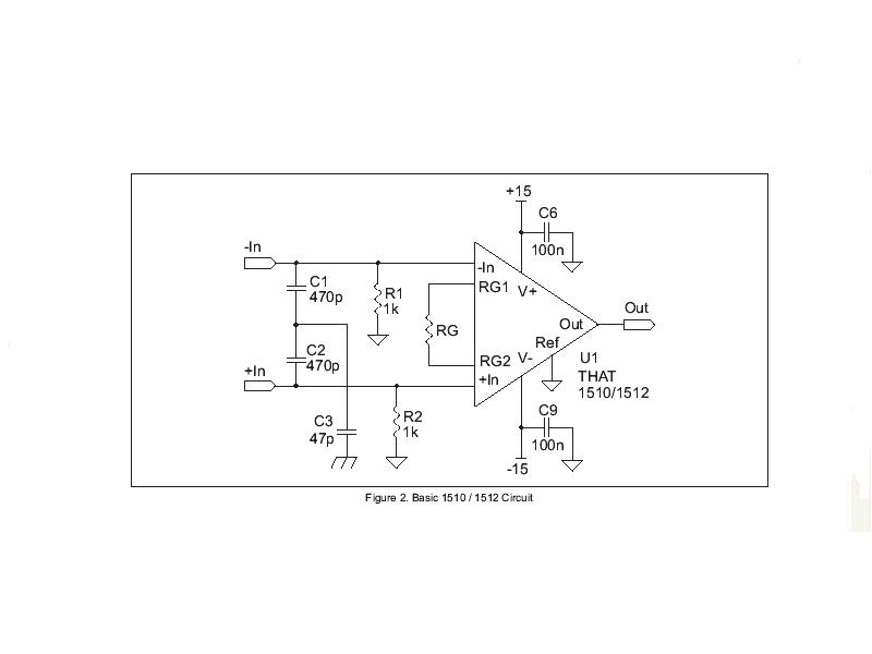
C6 & C9 are obviously for catching noise on the powerlines, and should be mounted as close to the chip as possible, but C1, C2 & C3, would I be better mounting them on the XLR, or close to the chip?
This is the fixed gain circuit, just because I couldn't find a JPEG of the variable gain circuit, where RG is replaced by RG and CG to limit the DC gain.
Also C3 goes to chassis ground, whereas the other components are signal ground. Does this mean I have to tie every C3 to the chassis (maybe via the XLR) and leave the signal grounds floating and tie signal ground to chassis at one point only?
The previous statement is from a guy who records his own, and other projects for fun. No money is made.
Mouser say they have a little under 12,000The Scum wrote:Thanks for the schem!
Are J111's still obtainable?
Last time I met with a Fairchild rep, they were telling me that all through hole parts were going to be EOL very shortly.
http://www.mouser.com/ProductDetail/Fai ... WWZw%3D%3D
The previous statement is from a guy who records his own, and other projects for fun. No money is made.
a dime from mouser in quantity at the moment - easy to believe they'll be disappearing, though! kind of a shame, but i guess the market's too small for big companies to think about.The Scum wrote:Thanks for the schem!
Are J111's still obtainable?
Last time I met with a Fairchild rep, they were telling me that all through hole parts were going to be EOL very shortly.
C1,2,3 are an RF filter on the input. they should be mounted directly on the jack to minimize inductance between the filter and your chassis (this is why c3 is tied to chassis directly).Drone wrote:C6 & C9 are obviously for catching noise on the powerlines, and should be mounted as close to the chip as possible, but C1, C2 & C3, would I be better mounting them on the XLR, or close to the chip?
the circuit's ground and chassis will have to be tied together at some point; a conventional choice is at the screw where your safety earth is bonded to chassis. i wouldn't worry about the particular choice too much, though, until you find there's some problem arising from it...
Cool, I'll make sure and get XLR's with a ground tab then, I can maybe even stick the 1K's on them. I need to figure out what I'm going to use a PSU, whether it will be onboard or external, and enclosures and stuff. I think I'll also pick up some JFET's from Mouser when I get the THAT chips. I also have a bunch of 6BZ6's that I may try and use, so I can try all three designs at some point.dfuruta wrote:C1,2,3 are an RF filter on the input. they should be mounted directly on the jack to minimize inductance between the filter and your chassis (this is why c3 is tied to chassis directly).Drone wrote:C6 & C9 are obviously for catching noise on the powerlines, and should be mounted as close to the chip as possible, but C1, C2 & C3, would I be better mounting them on the XLR, or close to the chip?
the circuit's ground and chassis will have to be tied together at some point; a conventional choice is at the screw where your safety earth is bonded to chassis. i wouldn't worry about the particular choice too much, though, until you find there's some problem arising from it...
Putting this at the top of my project list, who knows I might even get it done before 2017
The previous statement is from a guy who records his own, and other projects for fun. No money is made.
Some XLRs connectors have pin 1 connected directly to the shell, which would work fine too.Drone wrote:Cool, I'll make sure and get XLR's with a ground tab then, I can maybe even stick the 1K's on them.
1k resistors should go to circuit ground, not straight to chassis.
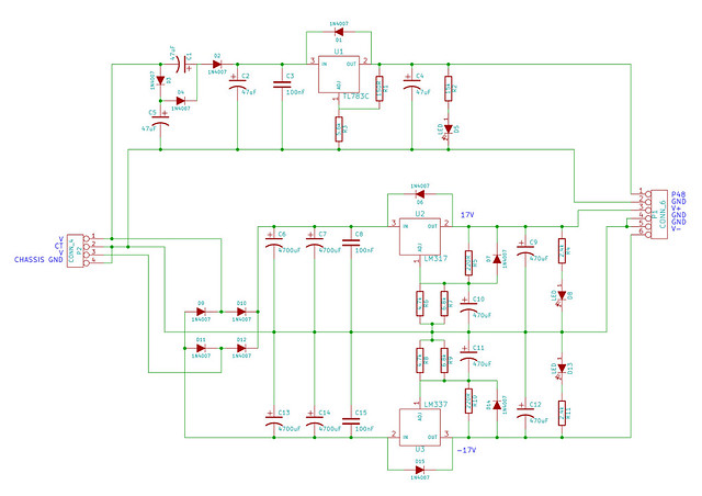
Here's a simple, easy power supply I've used before that would work for the THAT chip. You could likely use less capacitance on the input without problems. I've used power transformers from Antek - they're cheap and work fine.I need to figure out what I'm going to use a PSU, whether it will be onboard or external, and enclosures and stuff. I think I'll also pick up some JFET's from Mouser when I get the THAT chips. I also have a bunch of 6BZ6's that I may try and use, so I can try all three designs at some point.
Do it up! It's nice to record with something you built yourself.Putting this at the top of my project list, who knows I might even get it done before 2017
-
Jim Williams
- tinnitus
- Posts: 1135
- Joined: Sat Jun 03, 2006 8:19 am
- Location: beautiful Carlsbad, CA
- Contact:
That is a standard power supply design. Use Linear Tech LT1033 negative and LT1086 regulators for better ripple control and less output noise. I would also place 4700uf/25V caps on the regulator's outputs, that will reduce the regulator's noise to almost nothing.
Use fast recovery 1N4934 rectifier diodes as they generate less high frequency noise. Use WIMA MKP poly caps as bypasses, those will filter out all the AC line noises and spikes.
Use fast recovery 1N4934 rectifier diodes as they generate less high frequency noise. Use WIMA MKP poly caps as bypasses, those will filter out all the AC line noises and spikes.
Jim Williams
Audio Upgrades
Audio Upgrades
-
Jim Williams
- tinnitus
- Posts: 1135
- Joined: Sat Jun 03, 2006 8:19 am
- Location: beautiful Carlsbad, CA
- Contact:
Who is online
Users browsing this forum: No registered users and 70 guests