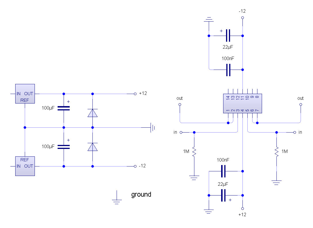
rj if you look at the datasheet for the 074 you will see a diagram that shows the pins of the chip to use. the triangle is just a universal op amp diagram. the symbols are drawn that way so that the design can be applied to any op amp and you just have to use different pins.
http://pdf1.alldatasheet.com/datasheet- ... TL074.html
as for being a caveman, i tough myself this shit over the past and half so it can't be that hard.
COMPLETELY IGNORE THE INVERTING BUFFER and anything to do with it. it is extra and should only be used if you want to add the inverting feature to each mod output so you will have 4 mod sources out the back instead of two. not sure why it was brought up before but i though i explained that it was not to be used as the main inverter.
" NON-INVERTING input, or INVERTING input? "
(-) = inverting input
(+) = non-inverting input
so if you reread the second post he is just telling you to make a normal non inverting buffer. also you will want to find some smaller ceramic caps anywhere around 100n and use those right next to the TL074?s from each power pin to ground or you might get some noise and hash and shit. do it in the same why that you have the 22u but right next to the chip. then also just at the + input of each buffer you should do what brian said and have a 1M resistor to ground so there is a bias / ground reference of some sort for the op amps or they could act crazy. other then that one 1M resistor on each input you should not have ANY other resistors at all unless you really ?need? to invert the voltage, which doesn?t make any sense to me
the board isn?t sending me reply notifications anymore so i didn?t see this? anyone else having this happen?
steven
can anyone help me find a voltage follower-type op amp?
-
earl parameter
- buyin' gear
- Posts: 514
- Joined: Mon Mar 08, 2004 2:36 am
steven, thanks a bunch. after reading the posts over, and looking at your diagrams, i think i can now make sense of the icons in the diagram.
QUESTION: so i should NOT be wiring the master synthex opamp as non-inverting, and the slave opamp as inverting?
when the master synthex pitch mod pushes the voltage up or down, i want it to also push the slave synthex the SAME direction, not the opposite. (a synthex tech had told me to do 1st one non-inverting, and the 2nd one inverting,thats why i did that.)
-
The Scum
- mixes from purgatory
- Posts: 2750
- Joined: Thu Jul 03, 2003 11:26 pm
- Location: Denver, CO
- Contact:
Without knowing exactly where it sits in the circuit, my guess is that you want them both to be the same...either both inverting, or both non-inverting. Think about it this way: you invert it once, it's upside down. Invert it again, and it's right side up again. Or else, never invert it, and you're still OK.
I'd lean towards non-inverting first, because it uses fewer parts.
Give it a try, and if it's backwards, then change one side or the other.
Crashsick, what are you using to draw dem diagrams?
I'd lean towards non-inverting first, because it uses fewer parts.
Give it a try, and if it's backwards, then change one side or the other.
Crashsick, what are you using to draw dem diagrams?
-
earl parameter
- buyin' gear
- Posts: 514
- Joined: Mon Mar 08, 2004 2:36 am
"synthex the SAME direction,"
then no, if you invert the source then its now "down" instead of "up" etc... you could use the other amps you have on the other side of the chips to give you an inverting output TOO so you can use it to good effect, and it can get you interesting results, but you don't "NEED" to and it sounds like you don't want to. but i would myself just to not waste the OPA's and to have the extra outs. like mod the cutoff and pitch in opposing directions from the same source. good stuff. are you using 1/4" to connect between the synths?
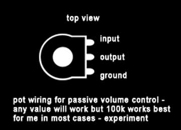
something else you might want to consider doing is adding a simple pot to give you a depth control for each of your new mod outputs. very easy just follow this diagram and place it in + path before the input of each buffer - but understand the "input" of the pot in this diagram is the input of the POT not the buffer circuit. so into the input of the pot and then out of the pot and into the input of the buffer. i can draw that up for you too if you want very useful
"what are you using to draw dem diagrams?"
http://www.new-wave-concepts.com/pr/wizard.html but i'm not happy with it's pcb conversion at ALL. i just didn't like eagle and i'm cheap - i need to find something else
steven
then no, if you invert the source then its now "down" instead of "up" etc... you could use the other amps you have on the other side of the chips to give you an inverting output TOO so you can use it to good effect, and it can get you interesting results, but you don't "NEED" to and it sounds like you don't want to. but i would myself just to not waste the OPA's and to have the extra outs. like mod the cutoff and pitch in opposing directions from the same source. good stuff. are you using 1/4" to connect between the synths?
something else you might want to consider doing is adding a simple pot to give you a depth control for each of your new mod outputs. very easy just follow this diagram and place it in + path before the input of each buffer - but understand the "input" of the pot in this diagram is the input of the POT not the buffer circuit. so into the input of the pot and then out of the pot and into the input of the buffer. i can draw that up for you too if you want very useful
"what are you using to draw dem diagrams?"
http://www.new-wave-concepts.com/pr/wizard.html but i'm not happy with it's pcb conversion at ALL. i just didn't like eagle and i'm cheap - i need to find something else
steven
OMFG!!!!! IT WORKS!!!!!!!!!!!!!!!!!!!!!!!!!!!!!!!!!!!!!!!!!!!!!!!!!!!!!
i followed crashsick's above diagram to a T.(thanks man, you are a lifesaver!!!) piece by piece, i finally got an understanding of how to read those kinds of diagrams. 2 final things:
1)-i still have a 100ohm resistor on each output of the MASTER synthex. the output jack is a midi jack i converted. i was advised to do this by a tech, in case i plugged in a bad cable. should i remove these resistors?
2)-the pitch bend mod works PERFECTLY-it will send out any range of 2.6V for down, to -4.0 volts for up. however, the mod/osc bend is doing something funny:
-for MOD, the board should send -12. for OSC, it should send +12. OSC works perfectly-any gradient between 0 to 12V is sent, just as it should. but for some reason, the MOD output reverts to a + singal when it hits -10.5V. so, if you slowly push the joystick to MOD, the opamp will send 0V, -1V, -2V, -4V, -6V, -8V, -10V, -10.5V, +10,5V, +11V, +11,19V.
i double checked the output of the actual mod board, and it doesnt do this. so its definitely an opamp thing. any ideas why its doing this, or how to change it? it causes the MOD to actually flip over to OSC obviously, which isnt exactly what it should do.
MY GOD YOU PEOPLE ARE FUCKING AMAZING! seriously, you have no idea how cool this is. you have now most likely given me the first ever Elka Synthex that can send pitch/mod info to another Synthex. these things are savagely powerful synths, that you just put over the top! CANT THANK YOU ENOUGH!
-
earl parameter
- buyin' gear
- Posts: 514
- Joined: Mon Mar 08, 2004 2:36 am
"should i remove these resistors?" nah its a good idea.
using a din (midi) jack is a good idea but you just cut out the chance to have other outboard LFO's be fed to the inputs. i would have used 1/4" and just labeled them and never plugged in anything over 12v
"the MOD output reverts to a + signal when it hits -10.5V." and you did not use the little over voltage protection scheme right? you should NOT use it for that input it will cut off all negative voltage
-
earl parameter
- buyin' gear
- Posts: 514
- Joined: Mon Mar 08, 2004 2:36 am
its a pretty odd result. i can only guess at things to look for while i think about how it could happen. are you 100% sure that -12v to the chip is not plugged into ground and ground is wired to -12?
do you understand that -12 is lower then 0 ? sorry if thats obvious but i have to ask
triple check all of your work from pin outs to solder bridges, shorts or fray's in wires everything
it really sounds like you have an accidental comparator happening - are the 1Ms tied to ground and not -12. is there anything at all touching the inverting (-) input of the op amp?s, there could be something in the original design where you are inserting the voltage that is pulling it to the other rail? where are you inserting it exactly? do you have one of those 100 ohm on the output between the buffer and original circuit?
my suggestion of the zener having anything to do with tis was stupid by the way and wouldn't cause this to happen if you did - but don't
steven
-
The Scum
- mixes from purgatory
- Posts: 2750
- Joined: Thu Jul 03, 2003 11:26 pm
- Location: Denver, CO
- Contact:
Congratulations, you have discovered JFET input related phase inversion.
From:http://www.analog.com/library/analogDia ... ary/6.html
From:http://www.analog.com/library/analogDia ... ary/6.html
You could probably fix this by adding a small resistor divider in front of the opamp where this is happening...like a 1K/10K. If you were really crafty, you could use a divide by 2 in the sending Synthex, and then a gain of 2 on the receiver.Q. What other features of op amps should the user know about?
A. A common problem encountered with JFET op-amps is phase inversion. If the input common-mode voltage of a JFET op-amp approaches the negative supply too closely, the inverting and non-inverting input terminals reverse functions. Negative feedback becomes positive feedback and the circuit may latch up. This latchup is unlikely to be destructive, but power may have to be switched off to correct it. This figure shows the effect of such phase inversion in a circuit where latch-up does not occur. The problem may be avoided by using bipolar amplifiers, or by restricting the common-mode range of the signal in some way.
-
earl parameter
- buyin' gear
- Posts: 514
- Joined: Mon Mar 08, 2004 2:36 am
interesting - and lame as fuck if thats whats happening but he said that his +V is switching to -V not the other way around?
if it is then you could replace the tl074 with a cmos op amp - not sure which one though i don't have much experience with them yet, maybe someone could chime in here? but if you can find one that will run on over -/+12v then most 14 pin DIP version should work as a drop in replacement for the tl074 with not changes at all. except you might want to have each of unused outputs on the other side connect to ground. i looked but i couldn't find anything right away. i don?t the time right now
if its not that though i was thinking that you could have at some point connected the pos and neg backwards to the chip and damaged it. this is very very easy to do and the results would be unpredictable so maybe try to replace the TL074 with another just to be sure
i?ll check back later
steven
ok-thanks guys. some updates:
1-to clarify, the master opamp's OUTPUT 2 is inverting from - to + at the END of the - range. OUTPUT 2 does NOT revert from + to - at the END of + range.
2-master opamp's OUTPUT 1 does NOT do this. (although, this might be moot, because output 2 only does this at -10.5V; output 1 only ranges from -4 to 2.7).
3-i have quadruple checked the master opamp V+ and V-. using chassis as ground, + is +12V, - is -12V. if i use the circuits "ground" lead which comes from the "0" pin on PSU, i get same readings.
SCUM-per my caveman EE, what is a "resistor divider?" if you can break that down in a form fitting a 7 year old, i can probably ask my nieghbors 7 year old to explain THAT to me. gracias!
(EDIT-I JUST GOOGLED THIS, I UNDERSTAND THE DIAGRAM OF A VOLTAGE DIVIDER, BUT WIKIPEDIA SUGGESTS NOT USING A VOLTAGE SOURCE. GOOD OR BAD?)
-
The Scum
- mixes from purgatory
- Posts: 2750
- Joined: Thu Jul 03, 2003 11:26 pm
- Location: Denver, CO
- Contact:
That definitely sounds like input phase inversion to me. Try swapping the opamps between the sources: use the bend one for modulation, and vice versa. Does the symptom follow the modulation source, or the opamp channel?
Rather than try to hash through divider theory, I'll just point you at a reasonably detailed source for that:
http://en.wikipedia.org/wiki/Voltage_divider
Just drop one of those in between the mod source, and the input of your opamp.
And then, since the voltage you're sending will less than it was, you could add some gain to the receiver opamp to make up for it. Look at the noninverting opamp circuit here:
http://en.wikipedia.org/wiki/Operationa ... plications
-
earl parameter
- buyin' gear
- Posts: 514
- Joined: Mon Mar 08, 2004 2:36 am
report #3392744232.
the voltage divider worked. however, i have not figured out yet how to boost the voltage on the other side per scums' wikipedia link. if i get some patience, i will wade further into the waters of evil.
i may or may not take the voltage divider out. one of the great features of this instrument is that the mod/osc features have an initial AND delta frequency, so you can set the joystick to increase in speed/frequency the amount of mudulation. the voltage divider lops off that top 10%, and the gradient of modulation doesnt come across with it in.
Who is online
Users browsing this forum: No registered users and 66 guests