Modifying DBX 163X
-
Sean Sullivan

- moves faders with mind
- Posts: 2555
- Joined: Sat Mar 31, 2007 2:24 pm
- Location: Nashville
- Contact:
Ferrite Beads ...Again
I'm new to the world of ferrite beads and I'm unclear on this question: Does the ferrite bead REPLACE C2 or does it BYPASS C2?
Thanks!
Thanks!
-
Sean Sullivan
- moves faders with mind
- Posts: 2555
- Joined: Sat Mar 31, 2007 2:24 pm
- Location: Nashville
- Contact:
Cart sharing / Project sharing for parts dbx 163 mod
Hey guys,
Just a thought, would it be possible for someone who has done the mod already to post the bom using the feature available on mouser , I think it's called cart sharing or project sharing, making it a bit easier to place an order for the suggested parts to mod the dbx 163?
after reading... I think this is the recommendation from Jim Williams
Ferrite beads are Panasonic with leads, get those from digi-Key.
Remove C1
Use the ferrite bead for C2
100k for R2
Add 10 pf from pin 1 to 2 on OA1
C3+4 to .1 uf mono ceramic
C5 = 3.3uf Wima MKS-2 with .01 uf MKP-2 bypass.
Remove R9 and 10 unless you have a THD analyzer.
Remove C7
C4 = 47 pf NPO
C9+10 .1 uf mono ceramic
C24,25 Wima MKP-2 .01 uf
Add a 1 uf mylar across R15
C28, 29 1000 uf 25 v Nichicon
C32, 33 Panasonic FM 470 uf 25V
Change VCA to that 2180 or 2181
Add a 22 pf NPO cap across R23
Add a 47 pf NPO cap across R46
Add a 47 pf cap across R46
Change OA3 and OA4 to LT1124 or similar low noise precision opamp.
Install Machine sockets for audio opamps, you can use just about anything there you want. OA1 is dual, OA2 the output is single.
Just a thought, thanks for all the great info everyone has provided.
Re: Cart sharing / Project sharing for parts dbx 163 mod
A little while back I was lucky enough to buy an Audio Upgrades-modded DBX 163x on eBay. I was hoping for a dual channel compressor, so eventually I found an unmodded 163x and figured I'd try my hand at matching it to the Audio Upgrades version.
So I'm sitting in front of an unmodded (Made in China) 163x, a modded (Made in Taiwan) 163x, a (correct) schematic, and the lists of mods that both Jim W and Sean S suggest in this thread. I'd figured it would make my life easier, but not everything adds up cleanly, and I'm hoping someone can help me understand.
I should say that I hope this doesn't seem nitpicky or ungracious in the face of all this sage advice. I've built some kits before but I'm pretty much a neophyte and am really trying to make sense of this stuff. Some may be typos, but I suppose it's possible that the Jim Williams mod I own was uniquely suited to a customer's request and if I follow Jim's Tape Op advice I will end up with an unmatched pair. (In which case, should I mod the Audio Upgrades modded unit as well?!?!) Lastly, maybe this attempt at further clarity will help others doing the mod.
I'll call my 2 units 163X and 163X-JW for convenience sake. Here's the inconsistencies:
JW says "Remove C1" with no further instruction. 163X-JW has a "22j" ceramic cap.
JW says "C9+10 .1 uf mono ceramic". 163X-JW uses these on C8 and C9, C10 seems untouched.
JW says both "C4 = 47 pf NPO" but I think he means C6 here. He's already told us what to do with C4 and my 163X-JW uses this in C6.
JW says "C24,25 Wima MKP-2 .01 uf", but 163X-JW uses these on C26-27 and leaves 24-25 alone.
JW says "Change OA3 and OA4 to LT1124 or similar low noise precision opamp." 163X-JW uses 4558, just like 163X, albeit from a different maker.
If I'm reading the chips right, 163X-JW uses what appears to be a 4051 for OA2 and 4052 for OA1. Whatever I'm looking at has 8 pins, but when I look up 4051 and 4052 on the internet, these chips have 16 pins.
I also note that Sean's suggestions replace IC2 with a THAT 2180a but does nothing to IC1 (the VCA), whereas Jim only mods the VCA, using the same 2180a. I don't know if that is a typo from Sean or a difference of opinion.

-
doc sherm sticks
- audio school
- Posts: 3
- Joined: Mon Nov 15, 2010 5:18 pm
hey sorry for hijacking a tiny bit, but i dindt want to start a new dbx thread....
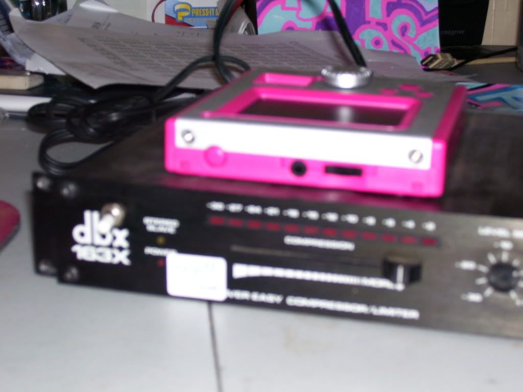
so i just picked up a used 163X at my local store (its my second 163x) and it has a 3 way toggle switch that was added on the front by someone...the guy at the store didnt know what it did....i was wondering if anyone around here might know what this "mod" does? i searched the web and found this forum but didnt find any info on a toggle switch mod.
i thought it might be a power on/off thing but na its not. i havent tested it yet to see if the sound changes when u change the position of the switch yet as i just got home from work, but i figured htis might be a good place to start as there seems to be a lot of knowledge folks here and a lot of threads pertaining to the 163x...
here is a pic of the switch to get an idea...white switch is right above the dbx logo.
http://i268.photobucket.com/albums/jj14 ... 1289871941
i figure u may need a gut shot to determine what this is, hoping i dont havta break this lil guy open tho. if it would help let me know and i can take some gut shots.
thanks!
-
doc sherm sticks
- audio school
- Posts: 3
- Joined: Mon Nov 15, 2010 5:18 pm
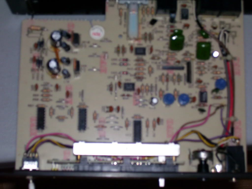
busted open! heres a photo of the inside...sorry for the blurryness, i took some others but they are even blurrier...
http://i268.photobucket.com/albums/jj14 ... 0_0424.jpg
so u can see the switch on the left with the yellow, pink and brown wiring. it goes to the hi-z input on the front as well as that resistor there, R17. it looks to be the same resistance as the one above R16. it looks something like gold, black, red, red.
the resistor is lifted up and it connected via the brown and purple wiring which connect to the switch, the pink wiring goes from the board where the end of the lifted resistor used to be, to the switch and then of the last two wires from the switch, one goes to the input on the front and the other goes to ground.
my guess is that one of the functions of the switch bypasses this resistor?
any ideas?
Who is online
Users browsing this forum: No registered users and 85 guests