Modifying DBX 163X
-
doc sherm sticks
- audio school
- Posts: 3
- Joined: Mon Nov 15, 2010 5:18 pm
-
Beneficial
- pushin' record
- Posts: 215
- Joined: Sat Sep 11, 2004 5:38 pm
- Location: Atlanta, GA
-
Beneficial
- pushin' record
- Posts: 215
- Joined: Sat Sep 11, 2004 5:38 pm
- Location: Atlanta, GA
-
Beneficial
- pushin' record
- Posts: 215
- Joined: Sat Sep 11, 2004 5:38 pm
- Location: Atlanta, GA
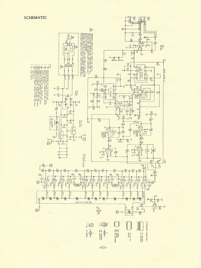
Here's the inside of my DBX 163. I'm wondering what all of these trim pots do. I know one of them adjusts third harmonic distortion (Jim Williams modded some of these for me in the past and told me that). Does anyone know which trim pot does that, or what the others do?
Looks like there are seven trim pots all together... five horizontal marked 50k, one marked 100, and then one bigger verticle one marked 50k. Is the blue stuff just wax that you can heat before you tweak the trim pot?
 [/img]
Looks like there are seven trim pots all together... five horizontal marked 50k, one marked 100, and then one bigger verticle one marked 50k. Is the blue stuff just wax that you can heat before you tweak the trim pot?
[/img]That's a very different implementation than the 163X, which is what I have, and what most everyone on this thread has. I can't tell you what trimmer is what, but this will:
http://www.dbxpro.com/product_downloads ... ematic.pdf
As far as rigging it to do distortion, I have a hunch mis-adjusting the THD trimmer will only get you asymmetrical clipping. For something closer to symmetrical clipping or full-on distortion, I think you would want to decrease the series resistance at the input of the VCA. But I'm just hypothesizng here, never actually tried it. . . .
Joe
-
Beneficial
- pushin' record
- Posts: 215
- Joined: Sat Sep 11, 2004 5:38 pm
- Location: Atlanta, GA
Interesting, I was thinking I could use them to add subtle third harmonics. I sent Jim an email, I've hired him to mod a bunch of stuff and he's an expert on these... hoping he gets back to me. It would be awesome if some of the other trim pots controlled attack/release etc, but I'm guessing that's not the case.

-
Beneficial
- pushin' record
- Posts: 215
- Joined: Sat Sep 11, 2004 5:38 pm
- Location: Atlanta, GA
I wonder if these 163's were made differently at different times. If someone has any ideas as to what these pots might do (or can make sense of the schematics posted above) please let me know. I'm tempted to start messing with them but don't want to throw it completely out of wack without knowing what they do.
Not sure if the 163 had variations/revisions, but it's very different from the 163X. The older 163 circuitry is closer to a discrete implementation, the in/out connectors are RCA, and the case has wood sides. The newer 163X uses an intergrated circuit VCA and a later generation integrated RMS detector chip, 1/4'' connectors, and a standard half-rack case made of metal. . . .
Here's the calibration notes for the 163:
http://www.dbxpro.com/product_downloads ... cedure.pdf
It says the THD adjustment sets the 2nd harmonic distortion, which is (as I said) a product of asymmetrical clipping. 3rd harmonic distortion would be a product of symmetrical clipping, and you would get this most easily by overdriving the input of the VCA. . . .
The other trimmers adjust PS voltage, DC offset, output level, etc. Probably no need to mess with those. . . .
Joe
-
Beneficial
- pushin' record
- Posts: 215
- Joined: Sat Sep 11, 2004 5:38 pm
- Location: Atlanta, GA
Thanks for posting that calibration link! I emailed Jim Williams asking about this and he told me not to mess with it. It looks like distortion is adjusted by a combination of three different trim pots. I might get brave enough to start messing around with it. Hopefully I don't throw it too out of wack.
Help me troubleshoot one of these please!
I modded a pair of these and was very pleased with the results. Until recently that is.
After a couple of months of use, one day one of the unit's red leds looked dim, and the unit wouldn't pass signal. I opened the thing up and started probing the test points.
Test points 7 + 8, which should show + and - 24V, show 12V and -2.3V respectively. There's not much between them and the power transformer (which appears to be fine, it powers the working unit) except diodes, and they tested okay, in circuit at least.
Farther down the line, test points 9 + 10 show 10.2V and 0V. I swapped out VR2 (voltage regulator?) with the component from the good unit, but no dice. I also decoupled these points from the rest of the unit in case something further down the line was dragging down the power supply, but again no dice.
Anyone have any clues? Troubleshooting is a weak point of mine and frankly, I'm stumped.
P.S. - Tried to include a .jpeg of the schematic but for whatever reason that's proving difficult. Links to schematics are below.

http://img.photobucket.com/albums/v295/ ... c/163X.jpg
http://www.dbxpro.com/product_downloads ... ematic.pdf
After a couple of months of use, one day one of the unit's red leds looked dim, and the unit wouldn't pass signal. I opened the thing up and started probing the test points.
Test points 7 + 8, which should show + and - 24V, show 12V and -2.3V respectively. There's not much between them and the power transformer (which appears to be fine, it powers the working unit) except diodes, and they tested okay, in circuit at least.
Farther down the line, test points 9 + 10 show 10.2V and 0V. I swapped out VR2 (voltage regulator?) with the component from the good unit, but no dice. I also decoupled these points from the rest of the unit in case something further down the line was dragging down the power supply, but again no dice.
Anyone have any clues? Troubleshooting is a weak point of mine and frankly, I'm stumped.
P.S. - Tried to include a .jpeg of the schematic but for whatever reason that's proving difficult. Links to schematics are below.
http://img.photobucket.com/albums/v295/ ... c/163X.jpg
http://www.dbxpro.com/product_downloads ... ematic.pdf
Most likely C29 has failed short, since your unregulated negative rail is sagging so much. If you check it closely, you may be able to see it leaking from the top or bottom. If it were me, I'd replace all the rectifier diodes (CR21 thru CR24) and all the electrolytics in the power supply (C28 thru C33.)
If you need to order parts, I'd swap the diodes for UF4007 instead of the stock 1N4002, and put 680uF 35V caps in place of C28 and C29. I'd also add .1uF C0G/NP0 ceramic bypass caps in parallel with C28, C29, C32, and C33.
If you need to order parts, I'd swap the diodes for UF4007 instead of the stock 1N4002, and put 680uF 35V caps in place of C28 and C29. I'd also add .1uF C0G/NP0 ceramic bypass caps in parallel with C28, C29, C32, and C33.
Thanks for that, I didn't check the PS electros, other than verifying the solder joints. They're all new and higher capacity than stock, but I suppose there's no reason a new capacitor can't fail just as well as an old one....
Update: C29 (and its bypass) check okay, and swapping in a replacement doesn't cure the problem. I'll replace the diodes, but I'm wondering--and this belies my troubleshooting inexperience:
It seems that the problem starts as soon as AC hits the PS. So it would be my instinct to focus my attention there (though the diodes appear fine).
But is there something down the line (the led board? The "Q1" transistor?) that's "weighing" down the 24V PS?
Or is the simplest answer usually the right one?
Who is online
Users browsing this forum: No registered users and 53 guests