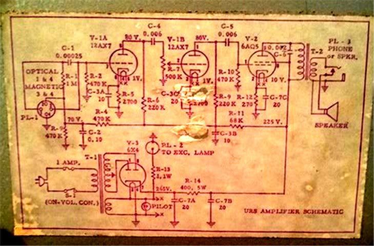
Here is a schematic:
Here are some recommendations that I've gathered:
"Remove C1. When changing the connector, connect tip to pin 3, sleeve to pin 4. Change the volume pot to 1M."
"Recap the power supply then rip out everything in front of the first 12AX7 stage. Replace the 470K with 1 Meg and then add anything from 10K to 100K resistor to pad the input like any good old Fender."
"You want to remove from the original schematic completely as follows: PL-1, PL-2, C-1, C-2, R-1, R-3, R-4, and R-13."
"Replace C-4 and C-5 with .02uf 400+v caps, Orange Drop or similar. Replace the C-3 multi-cap with individual 25uf-50v caps at the 3 cathode bypass locations and the single 10uf-350+v filter cap."
Replace R-2 with a 1M resistor and R-7 with a 1M Log (audio taper) Pot."
"You DO really-want to disconnect the high voltage to the optical sound head, both where it comes off the B+ line and where the audio goes to the first tube. The "impedance" is fine the way it is. 1Meg, 470K, either is fine. The 68K (actually 34K) is useful when you go to different dives every night and one is under a radio tower (it cuts radio signals); but you don't go out much these days/nights. Go over to Radio Shack, get the 2-pack of 10 ohm 10 Watt resistors. Parallel them across the old speaker winding. The exact value is not too important, and we don't know if the amp was meant for 8 or 4 ohms. However we DO need "power". You may say one 6AQ5 only makes 4 clean watts, but when OVER-driven it makes nearly double that, so a 10W resistor. (At RS, the cheapest near-match is two 10r 10W for under a buck.)"