Correct RE20 / PL20 Wiring
-
mechanicalmastering

- takin' a dinner break
- Posts: 173
- Joined: Fri Jun 18, 2010 2:39 pm
- Contact:
Correct RE20 / PL20 Wiring
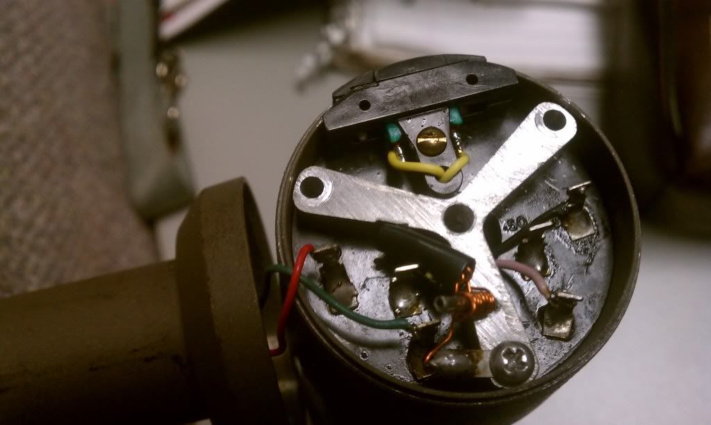
I just got a great deal on a pl20 cause the guy took it apart to change the foam and then forgot which wires went where. Here is a pic of the current incorrect wiring, (pink/black go to capsule, red goes to pin 2, green to pin 3, pin 1 is jumpered to ground). What's the CORRECT places these wires go? (FYI, I bent the copper ground pole so don't mind that). Thanx guys!
That wiring is correct, based on this diagram.
-
mechanicalmastering
- takin' a dinner break
- Posts: 173
- Joined: Fri Jun 18, 2010 2:39 pm
- Contact:
-
Nick Sevilla

- on a wing and a prayer
- Posts: 5595
- Joined: Mon Mar 03, 2008 1:34 pm
- Location: Lake Arrowhead California USA
- Contact:
http://www.coutant.org/evre20/pl20.pdf
Another diagram.
In your picture, it seems that the exposed copper wire (transformer ground) may be touching the green terminal, a the lower part. Those should not touch.
And it would probably be a great idea to not have that ground wire touch ground in to locations, only in one. Wrapped around that post might not be good...
The pink wire (blue) and black are correctly wired.
The two yellow wires are also correctly wired to the switch.
I would disassemble the whole mic and do a continuity check on the wires and on the transformer(s).
Cheers
Howling at the neighbors. Hoping they have more mic cables.
Won't matter. It will just flip the polarity. You would still get signal regardless of their position.mechanicalmastering wrote:Maybe the black/pink need to be switched around?
While that might be the case, even if it was touching the green terminal, that would only ground out one side of the signal. It would still produce signal, albeit unbalanced and about 6dB lower in amplitude.Nick Sevilla wrote: In your picture, it seems that the exposed copper wire (transformer ground) may be touching the green terminal, a the lower part. Those should not touch.
Just for testing purposes, I'd run the pink and black wires straight from the capsule to the the XLR (pins 2 & 3), bypassing the transformer altogether, just to see if the capsule works.
-
mechanicalmastering
- takin' a dinner break
- Posts: 173
- Joined: Fri Jun 18, 2010 2:39 pm
- Contact:
Who is online
Users browsing this forum: No registered users and 220 guests