Recording Techniques, People Skills, Gear, Recording Spaces, Computers, and DIY
Moderators: drumsound, tomb
-
firgela
- pushin' record
- Posts: 235
- Joined: Sun Feb 15, 2004 9:49 pm
- Location: Orlando, FL
Post
by firgela » Sat Feb 03, 2007 7:36 am
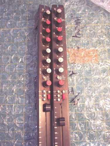
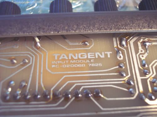
I recently picked up a pair of channel strips as a first "rack-em-up" project. I was told they came from a Tangent Series 4. There are 3 op amps (Motorola MC34001P) in them. I thought I'd start out with these on my first outing instead of jumping straight into a higher end project, the price was right and who knows, I may be pleasantly surprised. Any advice on how to get these dudes up and running will be awesome. I was wondering if peoples could suggest some reading material on the whys and wherefores of power supplies with an emphasis on audio... or maybe even a decent kit as a starting point. I exchanged a few PM's with Milkmansound and he recommended the JLM Audio AC/DC kit. He also mentioned using Altran xformers but suggested I look for something less expensive.... I agree since I'm hoping to use this project as a springboard.
Question: would I need a separate supply per channel?
I've had zero luck finding squat on the interweb about the particular mixer they came out of. The guy I got them from is supposed to be sending me the pin outs and schems for the power supply from a similar board. I'm still waiting for the schematics a few weeks later... I need to send him a reminder. I don't have a scope so..... yeah.
Thanks for your times.
(edit: right after posting this the schematics came in the mail, ha!)
"You can be a king or a street sweeper but everyone dances with the Grim Reaper"
-Robert Alton Harris
-
Kevin S
- gimme a little kick & snare
- Posts: 81
- Joined: Fri May 26, 2006 6:33 pm
- Location: Seattle, WA
Post
by Kevin S » Sat Feb 03, 2007 3:07 pm
http://www.edcorusa.com/
Inexpensive and sound pretty good.
You will need to find out what you need then call them and ask them what they have that does what your looking for.
I go some of there xs1100's for $45 for 2 shipped for a G1176 Ln1176 clone I'm building.
Info for that here :
http://www.gyraf.dk/ in the DIY section on the bottom.
You can get boards from Prodigy-pro forums in the black market for about $25 each.
Mnat from aUstralia sells a board for $22 AUD shipped and includes a unstuffed power supply board that may work for powering this up if you think you may want to do a LN1176 Clone.
-
Scodiddly
- genitals didn't survive the freeze
- Posts: 3984
- Joined: Wed Dec 10, 2003 6:38 am
- Location: Mundelein, IL, USA
-
Contact:
Post
by Scodiddly » Sat Feb 03, 2007 3:54 pm
Nice place to start! I dunno if those modules are especially good, but they're likely pretty decent and you can learn a lot in the process.
You'll only need one supply, just with enough capacity to run both modules. That's no big deal, they won't draw much power anyway. The schematics will tell you what you need, but for op-amp based stuff you'll most likely need something with +15 and -15 volt outputs, plus +48 for phantom power, and maybe some other odd voltage (like +5) if there's any logic stuff.
I'd start with the schematics and just start mapping out the connectors - if there's a big multipin or ribbon connector, figure out what all the pins do. That'll tell you where you need to hook up the power supply and where the inputs/outputs go.
-
firgela
- pushin' record
- Posts: 235
- Joined: Sun Feb 15, 2004 9:49 pm
- Location: Orlando, FL
Post
by firgela » Sun Feb 04, 2007 7:40 am
Thanks for the replies and please hang with me... plenty of more green questions to follow.
The datasheet for the ICs say the max input is +/-18v and the input range is +/-16v so, which is ideal? 18v or 15v per the schematic? I'd guess it's not a good idea to max something out when it's not really necessary (as you say they won't draw that much power anyhow)?
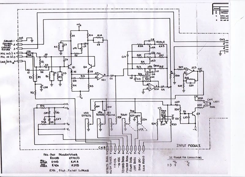
In the schematic (on bottom right) is this telling me the power input pins on the IC are pins 7 and 4, and does V2 mean a secondary voltage? Should I just ignore this... meaning, all I have to do is supply the +/-15 and the details work themselves out in the wash? Hmmmmm....
"You can be a king or a street sweeper but everyone dances with the Grim Reaper"
-Robert Alton Harris
-
RefD
- on a wing and a prayer
- Posts: 5993
- Joined: Fri Aug 27, 2004 9:10 pm
Post
by RefD » Sun Feb 04, 2007 8:22 am
firg, that looks like fun!
can't wait to see/hear the end result.
*keeps eye on thread*
?What need is there to weep over parts of life? The whole of it calls for tears.? -- Seneca
-
Scodiddly
- genitals didn't survive the freeze
- Posts: 3984
- Joined: Wed Dec 10, 2003 6:38 am
- Location: Mundelein, IL, USA
-
Contact:
Post
by Scodiddly » Sun Feb 04, 2007 8:45 am
Looks like phantom power would be "V1", making +/- 15 the "+V2" and "-V2".
You could skip the phantom supply for now, just do your testing with dynamic mics.
-
MD
- gettin' sounds
- Posts: 123
- Joined: Wed Oct 15, 2003 11:37 am
- Location: NY, NY
Post
by MD » Sun Feb 04, 2007 10:00 am
Looks like you'll just need to supply +/- 15 to pins 7 & 8 of the edge conenctor, and phantom to pin 9. (The center bottom of the schematic tells you what goes in or comes out of the 10 edge connector pins)
The lower left corner of the schematic shows the mini power supply buffer on each card. That has V1 before the on-board regulation and V2 after the regulation. V2 is then sent to the ICs.
Again, though, I think you don't have to worry about this. The strips should have an edge connector, and you just have to worry about what to feed that edge connector. (The schematic also tells you what outputs are available on what pins of the edge connector.)
-
brianroth
- tinnitus
- Posts: 1164
- Joined: Thu Dec 09, 2004 12:32 am
- Location: Oklahoma City
Post
by brianroth » Sat Feb 10, 2007 12:01 am
Since the module requires a bipolar +/- 15V supply, be sure to connect the "0 Volt/Common" from the power supply to the ground pin of the module. Oddly enough, it looks like it's NOT on that connector at the bottom of the schematic.
If using this for a pair of independent mic preamps, you will need to bypass one of the pots (like the echo send) and it's associated bus resistor to get a proper output signal.
Bri
-
Kevin S
- gimme a little kick & snare
- Posts: 81
- Joined: Fri May 26, 2006 6:33 pm
- Location: Seattle, WA
Post
by Kevin S » Mon Feb 12, 2007 2:09 pm
which is ideal? 18v or 15v per the schematic?
follow the schematic.
In the schematic (on bottom right) is this telling me the power input pins on the IC are pins 7 and 4, and does V2 mean a secondary voltage? Should I just ignore this... meaning, all I have to do is supply the +/-15 and the details work themselves out in the wash? Hmmmmm....
That is specific to the IC's on the opamp
You may also note that the is a send and return loop in the circuit I would recommend using a 1/4" stereo jack that has a built in switch and connect those to that. If I am not mistaken Tip is Send, Ring is Return and they share the ground.
If you don't want that function of inserting something into the channels then you will need to connect pins 2 (channel Send) to Pin 3 (channel Return)
Here is a link to a inexpensive power supply kit
http://www.jlmaudio.com/JLM%20Power%20Supply.htm This includes your phantom power needs but will require a 24v torodial transformer like the amveco's that are sold through Digi-key, Go with a 25VA and you should more than enough power for the 2 units. Part # TE62065-ND
http://dkc3.digikey.com/PDF/T071/1915.pdf
Hope that helps..
You may also want to use the star grounding method.
-
RefD
- on a wing and a prayer
- Posts: 5993
- Joined: Fri Aug 27, 2004 9:10 pm
Post
by RefD » Mon Feb 12, 2007 3:37 pm
apparently firgela can no longer log on to the board.
he has emailed the admins repeatedly to no avail.

?What need is there to weep over parts of life? The whole of it calls for tears.? -- Seneca
-
brianroth
- tinnitus
- Posts: 1164
- Joined: Thu Dec 09, 2004 12:32 am
- Location: Oklahoma City
Post
by brianroth » Tue Feb 13, 2007 9:59 am
Have firgela email me and I will try to assist.
Bri
-
firgela
- pushin' record
- Posts: 235
- Joined: Sun Feb 15, 2004 9:49 pm
- Location: Orlando, FL
Post
by firgela » Fri Feb 16, 2007 1:52 pm
Rescued from inactive user island! Thanks Brain and Hillary... mostly Brian because Hillary's email hates mine. I bet the internet looks exactly like Tron.
Thanks everybody for the replies... I bought a supply from the local surplus store because I too was anxious to get started. Details when I have more time.
"You can be a king or a street sweeper but everyone dances with the Grim Reaper"
-Robert Alton Harris
-
RefD
- on a wing and a prayer
- Posts: 5993
- Joined: Fri Aug 27, 2004 9:10 pm
Post
by RefD » Fri Feb 16, 2007 3:16 pm
firgela wrote:Rescued from inactive user island! Thanks Brain and Hillary... mostly Brian because Hillary's email hates mine. I bet the internet looks exactly like Tron.
Thanks everybody for the replies... I bought a supply from the local surplus store because I too was anxious to get started. Details when I have more time.
welcome back!
your avaturd still gives me nightmares, but i love it long time.
?What need is there to weep over parts of life? The whole of it calls for tears.? -- Seneca
-
brianroth
- tinnitus
- Posts: 1164
- Joined: Thu Dec 09, 2004 12:32 am
- Location: Oklahoma City
Post
by brianroth » Mon Feb 19, 2007 1:51 am
Firgela, glad that the "board gurus" were able to sort out the login issues after I sent your problem notes to them. Welcome back.
I hope our suggestions work out for you, especially regarding the power supply.
I'm such a backward human...no idea how to make a 'dancing' avatar, but actually no real desire, either..LOL
I'll just stick with my mugshot....
Bri
-
syrupcore
- deaf.
- Posts: 1793
- Joined: Mon Mar 08, 2004 4:40 am
- Location: Portland, Oregon
-
Contact:
Post
by syrupcore » Tue Apr 17, 2007 11:36 am
firgela, how did these turn out? Did you ever figure out what board they're from?
Who is online
Users browsing this forum: No registered users and 357 guests