i want to undertake a wiring project that will essentially be wiring 4 leads of one synth to send output info(pitch bend/mod, in the form of DC voltage) to control another synth, identical make. i understand which leads need to be wired to which, however, i asked a knowledgeable synth tech about this and his response was "oh, well thats easy-just make sure you buffer both sides with a voltage follower-type op amp". the voltage variations that i measure from the pitch/mod section measure in the 0-15v range-specifically, 2 of them are in the 0v-6v-12v range, and 2 are in the 0-3-6 range, if i remember correctly.
my problem is that.....i dont know shit from shinola when it comes to op amps. can anyone point me in the right direction of what i need? thanks guys!
can anyone help me find a voltage follower-type op amp?
-
edanderson
- gettin' sounds
- Posts: 128
- Joined: Wed May 07, 2003 5:49 am
a voltage follower isn't really a type of opamp, but a way of hooking up an opamp (or other amplifier) as a unity gain buffer. what he's saying is that you should have a buffer on each input and output of each device you want to hook up. this will help prevent interference and interaction problems.
the basic idea will be to hook up an opamp with the output connected directly to the inverting input. this will set the gain at 1 and give you a "voltage follower" whatever the voltage you put in the NON-inverting input is what you get out. you can hook the V+ and V- on the opamp to the positive supply and ground in your synth.
try a TLO7x series opamp. one TLO74 chip has 4 opamps. they're cheap and should work okay as a starting point. put a 22uf cap from the V+ and V- to ground close to each chip.
ed
ok, 1 more question:
ive got these opamps wired up now, havent turned the unit on yet, cause i need to be 10000% sure i did this right before powering up:
the opamp specs say "18v". i found a lead on the PSU that reads 12v across it, and another lead that is also the NEGATIVE lead of an elec. cap. (circuit board connects this to several other negative leads, and i think is ground from the power xformer-black wire from it?)
the only leads i could find on the PSU that were close to 18v were the 12v one, and a 24v one-i figured 12 would be safer.
did i do this right?
You didn't say what type of synth you're trying to modify, but be very careful where you get your power from. If you have OpAmps, in the circuit, you probably will find +/-15V or +/-18v on the other Opamps in the circuit. Look for 2, 3 terminal voltage regulators and get your bipolar (+/-V) voltages there for your envelope follower. The black wire on the power supply is probably ground, but many Opamp circuits use a virtual ground, so you never really connect the ground directly to the chip. Do you have schematics for the synth?
Cary
Cary
-
The Scum
- mixes from purgatory
- Posts: 2750
- Joined: Thu Jul 03, 2003 11:26 pm
- Location: Denver, CO
- Contact:
You say you found 0V, +12V and +24V...it sounds like you've assumed the wrong reference for ground, and actually found a -12V/0/+12V supply arrangement. 0/+12/+24 is a fairly unlikely arrangement for a synth.
Just because it's tied to the negative lead of a 'lytic cap, doesn't mean that it's ground...the negative rail of the supply will have - cap leads on it.
Three things to try:
- Is there a pair of big caps somewhere near the power supply? You'll probably find that they're tied together...the + leg of one to the - leg of the other, and that connection runs a bunch of other places. That would be ground.
- If you can't find that, measure the voltage between the output jack sleeve and what you think are the power supply voltages. The sleeve should be tied to ground.
-If you're still not confident in the voltages you've found, get schematics, and use them to navigate. You might find they're on the web somewhere.
Can you post photos, and we can help doublecheck your work?
You put some supply decoupling caps on your new opamps, right?
thanks guys. it sounds like i may not be right here. tomorrow im gonna snip the power leads for the opamp, turn the synth on, and do some more measuring.
here is a link to the schematic for the Elka Synthex, PSU is one of the first pages, 5805 circuit board:
http://www.megaupload.com/?d=CLGKGCLV
1-caps:yes, i do have one 22mfd/35v cap with + connected to V+ of the opamp and - connected to V-.
2-there will be an opamp circuit on each of the 2 synths. this mod will be sending output voltages for pitch and mod from one to the other. i have the master synth opamp circuit as non-inverting, and the slave circuit as inverting, per ed's instructions.
3-you will see the power supply board has a bunch of voltage output pins-2.5,6,12,20. when i was checking all those pins for an 18v measurement, i was getting very similar readings to those numbers, and i was using the - pin of a 10,000mfd cap that i ended up wiring the - of the opamp to. so im 90% sure that at least the + is connected to that 12v output pin right now.
thanks a ton guys! hopefully back tomorrow with more info. the wealth of knowledge on TOMB is an unbelievable resource.
Page 3 of the linked schematic PDF *definitely* shows a set of +/- 12 VDC rails on the PSU section. That is where you need to look through. It appears that those two rails are referenced to a common which is tied to chassis. However, I would suggest connecting three wires (+12, -12, and common) as close as you can to the 78O12 and 78M12 regulators, perhaps right across the wiring leads of the 100 uF capacitors that are at the outputs of the regulators.
Bri
Bri
-
earl parameter
- buyin' gear
- Posts: 514
- Joined: Mon Mar 08, 2004 2:36 am
thanks guys, i appreciate all the help. crashsick-that's really kind of you to draw up the diagram. i wish i understood how to read diagrams better, so alot of it is lost on me, unfortunately. i am going to read it over some more and hopefully more will make sense.
1-brian-i only see 2 power leads on the opamp, V+ and V-. where would a third lead go?
2-if i were to connect the V+ of the opamp to the +12 lead on PSU, and V- to the -12 on PSU, would the opamp be getting 24V? (the only rating i see on the opamp is "18V"-im assuming 24v would be bad, right?.)
3-crashsick-the MAXIMUM voltage that will run through the opamp is 11.9. 9 (EDIT, THERE WILL BE A RANGE OF +11.9 TO -11.7 RUNNING THRU OPAMP, THIS RANGE IS OBVIOUSLY TAKEN FROM THE +12 AND -12 PINS ON THE PSU, AS THEIR ACTUAL READINGS ARE 11.9 AND -11.7)
sorry to break this down to such a basic level, but im very green on some of this stuff. thanks guys.
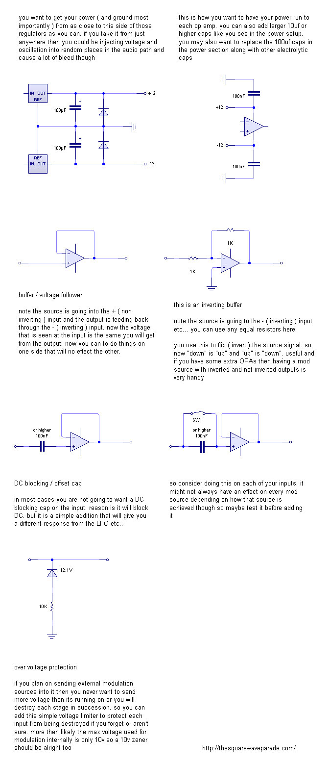
Crashsick...excellent post! Two comments. On the schemo for the non-inverting buffer, I suggest a high value resistor (100K to 1 Meg) wired from the non-inverting input pin to ground. This will prevent the opamp from going totally bonkers if the input node is accidentally (or intentionally) disconnected.
The Zener clamp is a good idea, but is only good for positive-going input voltages. A more complex clamp is required if the incoming signal goes negative.
RJD2....with my suggestion of a "bias" resistor from the non-inverting input to ground, then three points on the buffer card will be tied back to the ground/common point at the power supply. The grounded end of my suggested resistor, and the grounded ends of the two 100 nF (actual value non-critical, btw) power rail bypass cpacitors shown in Crashsick's second schematic.
Opamp ratings assume a bipolar (+/-) power supply and with most "generic" opamps I know of these days (there will be obvious exceptions!), +/- 18 V is a very standard maximum rating. You can think of that as a 36 V maximum. IOW, a maximum of 36 Volts as measured between the positive power supply pin on the chip and the negative power supply pin.
Look through the spec sheets for a TL0-71 or a LF-351 (very generic opamps that are almost twins in terms of performance).
I won't muddy the waters too much further <g>, but if you are requiring TWO buffer/followers, then the TL072 or LF-353 are identical performers, but have two opamps in the same sized package.
Mouser.com very kindly provides links to the spec sheets (in PDF) once you search for the part number.....oh yes, and you want the 8DIP (or DIP8) version package of the chips, and NOT the "SO" versions.
Bri
-
earl parameter
- buyin' gear
- Posts: 514
- Joined: Mon Mar 08, 2004 2:36 am
yeah i guess a pull down would be a good idea here. i was just keeping it simple. i can add it if you want
yeah right, the zener will remove all negative going voltages and i didn't know what was being sent the incoming voltage so for all i know it already had a rectifying diode at its input that could have been being bypassed by rj without us knowing what sort of clamp would work for both + and - ? to clamp at +/-12v could you make a zener diode ring, i?ve never seen one? i?d have to look around to make sure it can take negative voltage and send it along without damaging anything. its not like there is any logic to worry about though. habit i guess
"the MAXIMUM voltage that will run through the opamp is 11.9. 9" yes but depending on what OPA's are used, which i didn't bother checking sorry, they will not go rail to rail and most synth designs use a 10V or +/- 5v standard for internal modulation ( there are others though) so i was just saying that if you could only find a 10v zener you would still be fine. thats all
yes to clear up the power issue there are two DC power sources with one common half way point which is referred to as "ground". the term "ground" is just a reference point and does not always have to be zero. it is in most cases just the half way point between the two power rails and can be created in a couple different ways from a single DC source even and in those cases generally its referred to as Vref or virtual / reference ground. there are some chips that have a Vref built inside of them so you can feed them a single DC source and they create a bipolar setup with no extra components needed. this is used in pedal design all the time
in the case of the elka you are getting an AC power source, sending it to a step down transformer ( not sure of the voltage, at least 15v, probably 18v - most regulators need to be fed at least 3 v higher then they put out to work correctly ), and splitting up each half of the signal with the diode ring, then sending it to some 2200uf smoothing caps and then the + side is going to a 78012 positive regulator to give you a more precise "regulated" +12vdc further smoothed on the other side by the 100u cap and protected from reverse polarity by the diode to ground. the 79012 gives you the negative dc voltage with all the same setup and the center point with the ground symbol is the reference ground for the entire design
- hopefully that was clear. kind of cloudy today
steven
yeah right, the zener will remove all negative going voltages and i didn't know what was being sent the incoming voltage so for all i know it already had a rectifying diode at its input that could have been being bypassed by rj without us knowing
"the MAXIMUM voltage that will run through the opamp is 11.9. 9" yes but depending on what OPA's are used, which i didn't bother checking sorry, they will not go rail to rail and most synth designs use a 10V or +/- 5v standard for internal modulation ( there are others though) so i was just saying that if you could only find a 10v zener you would still be fine. thats all
yes to clear up the power issue there are two DC power sources with one common half way point which is referred to as "ground". the term "ground" is just a reference point and does not always have to be zero. it is in most cases just the half way point between the two power rails and can be created in a couple different ways from a single DC source even and in those cases generally its referred to as Vref or virtual / reference ground. there are some chips that have a Vref built inside of them so you can feed them a single DC source and they create a bipolar setup with no extra components needed. this is used in pedal design all the time
in the case of the elka you are getting an AC power source, sending it to a step down transformer ( not sure of the voltage, at least 15v, probably 18v - most regulators need to be fed at least 3 v higher then they put out to work correctly ), and splitting up each half of the signal with the diode ring, then sending it to some 2200uf smoothing caps and then the + side is going to a 78012 positive regulator to give you a more precise "regulated" +12vdc further smoothed on the other side by the 100u cap and protected from reverse polarity by the diode to ground. the 79012 gives you the negative dc voltage with all the same setup and the center point with the ground symbol is the reference ground for the entire design
- hopefully that was clear. kind of cloudy today
steven
yes, thanks guys. im slowly cobbling together an understanding of this. i made enough progress on this today to get up and running, however, im presented with a new problem. what i have now is this(diagram link):
http://www.megaupload.com/?d=TZDJUUQJ
sorry for the handmade drawing, i tried to highlight to make it easier to read.
the problem im having now is that BOTH of the synthex opamps are sending out a voltage on all their outputs with NO voltage being sent to their respective inputs(11.1V on the master synthex, -10.4 on the slave). what i NEED it to be doing is sending out 0 on all the inputs, and the pitch bend would modulate its from 4 to -2.7, and mod would modulate from 12v to -12v. using the joystick now doesnt modulate either of the voltages-they stay at 11.1V, or -10.4, constantly.
any ideas?
-
The Scum
- mixes from purgatory
- Posts: 2750
- Joined: Thu Jul 03, 2003 11:26 pm
- Location: Denver, CO
- Contact:
A couple ideas:
1> Do you have any sort of connection from the opamp outputs back to the -inputs? You'll notice in crashsick's pics that the non-inverting one just ties the output right back to the output, and the inverting one has a 1K resistor. I don't see these connections in your pic.
They're especially easy for the non-inverting opamp, because the output and -in pins are right next to each other.
2> You picture shows two unused opamps in each chip...if they're just left hanging, they can cause strange behavior. My recommendation would be to wire them both as non-inverting followers (output back to -input), following ground (+input tied to ground).
no, i dont have those connections. i'll be honest-i dont know how to read the diagrams that crashsick posted(sorry, im a caveman!) could you possibly dumb it down to something like "put 1k resistor across non-inverting input 1 and output 1. repeat for output 2"? im sorry, i am VERY VERY green on some of this stuff!The Scum wrote:A couple ideas:
1> Do you have any sort of connection from the opamp outputs back to the -inputs? You'll notice in crashsick's pics that the non-inverting one just ties the output right back to the output, and the inverting one has a 1K resistor. I don't see these connections in your pic.
They're especially easy for the non-inverting opamp, because the output and -in pins are right next to each other.
you are right-i l just left these open. this, i can do. just to clarify, when you write "(output back to -input)", the "-input" in question is NON-INVERTING input, or INVERTING input?The Scum wrote: 2> You picture shows two unused opamps in each chip...if they're just left hanging, they can cause strange behavior. My recommendation would be to wire them both as non-inverting followers (output back to -input), following ground (+input tied to ground).
SCUM, youre badass man. you've been a lifesaver more than once for me on here! thanks.
Who is online
Users browsing this forum: No registered users and 25 guests