
Sorry about thatThis is a topic that belongs in DIY gear if a moderator wants to move it.
I don't think a 10VA torroid is going to have enough juice to power this.sonicmook56 wrote:This one should be about right for your bi-polar supply.
http://www.antekinc.com/AN-01xx.pdf
Model AN-0112
and for your phantom supply:
AN-0118
I have used several of there transformers, there good and inexpensive.
~B
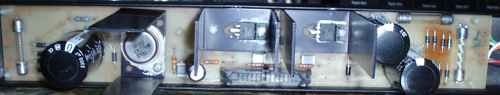
I wonder about this myself. The regulators that are in there put out 1.5 amps. But I also am not sure.I don't think a 10VA torroid is going to have enough juice to power this.
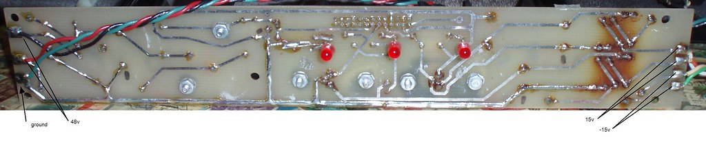
Yeah what's in the picture is all I have. Are you saying to get a power supply that gives me the DC voltages I need and just by passing what's here now?Are you saying there's no power transformer?
nate wrote:I don't think a 10VA torroid is going to have enough juice to power this.sonicmook56 wrote:This one should be about right for your bi-polar supply.
http://www.antekinc.com/AN-01xx.pdf
Model AN-0112
and for your phantom supply:
AN-0118
I have used several of there transformers, there good and inexpensive.
~B
Why did you recommend those specific models? How do you know what transformer secondary voltages are needed here? Did I miss a schematic somewhere?
I'm saying you've only got half a power supply there. There should be a pretty hefty transformer along with it.Yeah what's in the picture is all I have. Are you saying to get a power supply that gives me the DC voltages I need and just by passing what's here now?Are you saying there's no power transformer?
Users browsing this forum: No registered users and 164 guests