Recording Techniques, People Skills, Gear, Recording Spaces, Computers, and DIY
Moderators: drumsound, tomb
-
dbeck
- audio school graduate
- Posts: 24
- Joined: Sat Apr 04, 2009 8:45 am
Post
by dbeck » Thu Dec 10, 2009 2:41 pm
I'm using
this mod to allow the Realistic PZM to be phantom powered.
I'm to the step where the electret capsule needs to be modified and I'm not understanding the wording.
Remove the capsule plate from the boundary plate and remove the Electret insert and its associated circuit board. After removing the insert itself you need to cut the connection between the metal case and the black wire's terminal (do this very carefully!), then solder a small strand of wire to the case from the red wire's terminal.
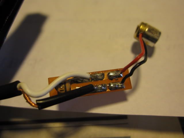
I'm assuming "Electret insert" means the microphone capsule (the thing on the far right in the picture below)
For one there's no metal case. So what does "CASE" refer to here?
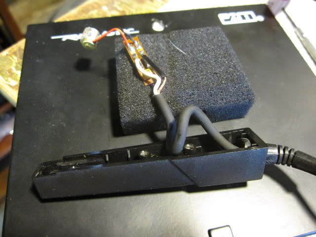
I'm reading this as cut the black wire between the microphone capsule and the circuit board and then make the red wire branch so that it connects to where the black wire WAS connected as well as it's current connection. Here are some pictures.
It feels weird for a mic to have only one wire coming from it. Dunno why.
-
strdsk
- re-cappin' neve
- Posts: 796
- Joined: Fri Oct 01, 2004 12:48 am
- Location: Illinois...near Chicago
Post
by strdsk » Fri Dec 11, 2009 9:35 am
Those were actually very nice sounding mics for the cash. I used to tape them to music stands with gaffer's tape to be able to vertically situate them near piano...an amazing sound!
Working on music with Pete from Porno for Pyros...
-
Scodiddly
- speech impediment
- Posts: 4001
- Joined: Wed Dec 10, 2003 6:38 am
- Location: Mundelein, IL, USA
-
Contact:
Post
by Scodiddly » Fri Dec 11, 2009 3:36 pm
Doesn't look like you've got the casing off the capsule yet.
But anyway, this is the mod where you reverse the connections to the FET buried inside the capsule. So you're leaving the black wire connected to its pad on the circuit board. The thing to cut is between where the black where is connected and the outside edge of the circuit board where it's crimped under the casing. Then you need to connect the casing to the red wire, while of course leaving the red wire attached to its original pad on the circuit board.
This changes the biasing in interesting and useful ways.
-
dbeck
- audio school graduate
- Posts: 24
- Joined: Sat Apr 04, 2009 8:45 am
Post
by dbeck » Sat Dec 12, 2009 12:47 am
Oh wow I was way off then. That thing is so tiny I didn't think we were supposed to go in there. Well I guess I get to use the magnifying glass on my extra hands soldering tool.
Thanks so much!
-
Scodiddly
- speech impediment
- Posts: 4001
- Joined: Wed Dec 10, 2003 6:38 am
- Location: Mundelein, IL, USA
-
Contact:
Post
by Scodiddly » Sat Dec 12, 2009 6:10 am
I should be more clear about the word "casing". The typical little Panasonic-style capsule that's probably in there has an aluminum (silver-colored) case, with a little hole at one end for sound and a circuit board over the other end. What I see in your pictures is a gold-colored thing that doesn't show the circuit board, so it's probably a case-around-the-real-case.
-
dbeck
- audio school graduate
- Posts: 24
- Joined: Sat Apr 04, 2009 8:45 am
Post
by dbeck » Sun Dec 13, 2009 8:06 pm
Hmmmm. So any tips on how to get in this thing? It's basically a solid piece with the mic underneath some sort of screen on one end and then the other end just has the wires sticking out. It's a solid piece as far as a I can tell.
-
Scodiddly
- speech impediment
- Posts: 4001
- Joined: Wed Dec 10, 2003 6:38 am
- Location: Mundelein, IL, USA
-
Contact:
Post
by Scodiddly » Wed Dec 16, 2009 5:58 am
See if you can (gently) pop the cap off the back.
Who is online
Users browsing this forum: No registered users and 98 guests