This is my first post here, so hello!! And thanks for having me.
I have this mixer and it is very sentimental. I had a lightning strike years ago and the board went out and an ex-employee that was a good tech had it up and running in about 15 minutes. I didn't think twice about it and was happy and since then I've lost touch with him. Anyway, this board has a separate power supply providing 48V Phantom and +/- 15 V on the rails for the Audio circuit. When I finally started using the board again after a long hiatus, the board typically would run for several days but would intermittently blow the audio fuses. I could put another set of fuses in and it wouldn't blow the fuse for sometimes days, sometimes weeks. Today the fuses blew and when I replaced I immediately could hear a "flickering" sound from the board (it was audio) and it blew the fuses. I unplugged the power supply from the board and the fuses don't blow. So I am thinking I now have to trace the audio section of the board. It has two 8 channel extensions so my first thought would be to remove one or both and see if the fuses still blow. If not then I can just work on the extensions. If so that would indicate the main board. The board with extensions is 32x8x2.
With that being said, I have a set of schematics I'm about to dive into but wanted to get anyone's incite that might be familiar with fixing / modding mixers on what would be the most logical thing to look for first. I have to clean the pots anyway so the board has to be maintenance and now, regrettably, fixed.
Thanks,
Jed
StudioMaster Series II Mixer Circa 1986
-
The Scum
- moves faders with mind
- Posts: 2746
- Joined: Thu Jul 03, 2003 11:26 pm
- Location: Denver, CO
- Contact:
First, with just the supply, check the VAC and VDC on the outputs. You want the VDC to be close to the rated voltage, and the VAC to be 0V.
If the supply outputs are high, address that problem before connecting the console. You don't want to use a supply that's turned into a killer. It'll just spread the problems around.
Visual inspections can be useful - look for scorched PCB or burnt components. Start with the supply, then check the desk itself. Power supplies on that era of desks are sometimes under-specified, run hot, and cook themselves to death. Sometimes it's a matter of a couple components (like bridge rectifiers in old Soundcraft supplies), sometimes the thing is a basketcase, and it's easier to replace from the ground up (like a Trident 24 or 65 supply).
If all that checks out, reintroduce the console in the smallest steps possible. If you can add one strip at a time, that will give you the best triangulation. I'm not sure what the thing is like inside, if there are individual PCBs that can be individually unplugged.
Monitor the voltages as you add the console back in. If they dip or you start to measure AC, you're on the trail of your problem. Feeling chips and stuff as you go can be informative - warm to the touch is OK, too hot to keep a finger on is a problem. An inline ammeter can also tell you when something is drawing too much current, but the blowing fuses are already telling you that...
Does the desk have any tantalum caps? They're notorious for failing shorted. Electrolytics are probably candidates for replacement, but they usually get noisy, rather than going short.
If you can isolate modules, you might be able to check continuity between the power pins and ground of individual modules. Sometimes you can locate a short that way.
"What fer?"
"Cat fur, to make kitten britches."
"Cat fur, to make kitten britches."
I don't know what kind of caps it has yet. I assume it definitely has electrolytics. How do you identify a tantalum cap? I've seen a mod on the board by Jim Williams where he recaps the supply to make it cleaner and less noisy. I didn't even think that maybe the supply is still bad even if not under load. I assumed since it didn't blow the fuse when I removed the load it was still good. Probably a very dangerous assumption and could be a big waste of time to overlook that. I'll start there tonite by measuring the voltage outputs as you suggest. I assume to clip a ground wire on and just probe the pins on the connector to the board? I'll open it up and see if I see anything burned looking first. I definitely don't want to tech the board if the supply is still iffy. Thanks. I hope I have time tonite but will let you know soon.
Jed
Jed
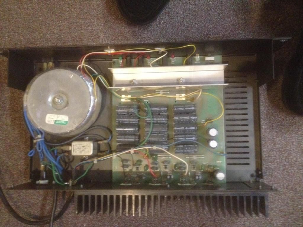
I'm hoping a guy on another forum will get me the schematic on the PSU. It's an EP3. I opened it up and looked on the board. Very very dusty. Where the transformer wires hit the board near the front panel LED's they have (will go look again to determine correct ACV because the lettering is small) posts that have expected AC voltages. Some of these didn't appear to read correctly. I'll have to put it on my scope, maybe my MM isn't dead on. At the points where the PSU feeds the console (DC Voltages) there were four posts that had 15V, 15V, -15V and 48V which is what the front of the PSU says. I checked those posts and they read 15.03VDC, 14.82VDC, -14.5VDC and 47.9VDC. I didn't read any AC on these posts.
This PSU has a TON of caps in it. I'll try and take a picture. It had a component between the power cord and transformer labelled WF130-6105 on it that I don't know what it is. I'm really hoping I can get a schematic. I noticed a resister towards the AC part of the circuit near the front panel LED's that looked discolored. I am going to replace it.
Should the voltages be that far off? They seemed steady though.
Jed
-
The Scum
- moves faders with mind
- Posts: 2746
- Joined: Thu Jul 03, 2003 11:26 pm
- Location: Denver, CO
- Contact:
The output DC voltages all look fine to me...well within a +/- 5% tolerance. No AC on them is more important than the exact voltages.
Watching them with a scope can verify that there's no ticks, clicks or pops that the meter misses.
The AC input voltages will likely read higher than labeled with the supply unloaded. Not a problem, just ohms law at work. They'll drop a bit as you add a load.
Do the rectifiers get hot?
Watching them with a scope can verify that there's no ticks, clicks or pops that the meter misses.
The AC input voltages will likely read higher than labeled with the supply unloaded. Not a problem, just ohms law at work. They'll drop a bit as you add a load.
Do the rectifiers get hot?
"What fer?"
"Cat fur, to make kitten britches."
"Cat fur, to make kitten britches."
Well...the one piece looks like a rectifier. The WF130 piece (http://www.alibaba.com/product-gs/58004 ... WF130.html). That is all I could find on it. I saw diodes near the DC outputs. Could it have more than one rectifier? The board looks like a pain to take apart because they have transistors on heatsinks mounted on the side of the box. Should I touch the chip that looks like a rectifier after it runs for a bit? How long should I turn it on "no load" before I can be confident that it is safe to start powering the board (assuming I can get it to even do that without blowing the fuses). And is there a way I can test the resistor in the circuit without removing it or should I just replace it? It is hard to tell but it looks like there is a slight burn on it but it could be just the way it looks.
Thank you for your help. I'm hoping I can get this board up and running. People say they are crap but I've always thought it sounded ok to my ears and very different than my digital setup.
Jed
Thank you for your help. I'm hoping I can get this board up and running. People say they are crap but I've always thought it sounded ok to my ears and very different than my digital setup.
Jed
-
The Scum
- moves faders with mind
- Posts: 2746
- Joined: Thu Jul 03, 2003 11:26 pm
- Location: Denver, CO
- Contact:
I would expect 3 rectifiers - one for the +/- 15, one for the other 15, and one for the 48. They may just be discrete diodes, and might be halfwave (2 diode) rectifiers for the unipolar rails.
The diodes near the outputs may just be some protection is things get mis-connected, keeping you form forcing current back into the outputs (say, if the 48 got accidentally shorted to a 15).
I think you're to the point that you can reasonably connect the console...it would be better if you can connect smaller increments...strip by strip, if that's possible.
I'd check continuity on the strip power rails before connecting them...if you see a dead short, don't plug it in.
Without knowing what it's doing, it's hard to know what's up with the burnt resistor...it might just be fallout from whatever's blowing fuses...or simply years of running warm.
Where in the circuit is the fuse the blows?
"What fer?"
"Cat fur, to make kitten britches."
"Cat fur, to make kitten britches."
It's always the audio circuit fuses that blow. It blew fast twice in a row the other night before I unplugged it for good. The first blow only took out one fuse and like a dummy I didn't note which. The second smoked them both. So I'm not sure if it's a single L/R problem or both. I may change out the resistor to be safe.
What do you mean by checking continuity on the rails? I don't have the PSU schematic yet and may not get it so it is hard to determine which pin is which without the pinout diagram on the 6 pin power connector.
I will take the extender units off the board and also see how much of the circuit can be unplugged to try to find the fault.
Thanks.
Jed
-
The Scum
- moves faders with mind
- Posts: 2746
- Joined: Thu Jul 03, 2003 11:26 pm
- Location: Denver, CO
- Contact:
Disconnect a module from the power supply. Then use an Ohmmeter to read between +V and ground, -V and ground, and +V and -V. I would expect a reading that slowly climbs toward infinity, as the current from the meter slowly charges the decoupling caps.What do you mean by checking continuity on the rails?
If something reads a solid, low resistance, then it's probably shorted. Tantalum caps are the #1 suspect...they look like little oblong blobs on 2 legs, often orange, green or blue.
The granularity of triangulation depends on how the console is constructed. If it's a single, large PCB, it's hard to track down...though sometimes there are jumpers you can cut or desolder to isolate sections of the board. If, by chance, it's a bunch of smaller circuit cards with ribbon cable or the like between them, unplug as much as you can, and work slowly.
Any chance for a photo of the inside of the desk?
"What fer?"
"Cat fur, to make kitten britches."
"Cat fur, to make kitten britches."
Yes. I'll pull it open this weekend and take some pictures. I'm pretty sure it is modular from what I remember. I can send a picture of the PSU today but the desk is very heavy so I will have to wait for a little help to get it situated. But at this juncture you are saying to work on the board and not the PSU right?
Jed
Jed
Ok. I unhooked the two 8 channel expanders and put the mixer on the bench. I haven't opened up the back but I will soon to get to the pots and give it a thorough cleaning. Anyway, I powered it and so far so good. It is holding power. I noticed one of the expander ribbon cables was kinked pretty good. I'm not sure if this is what caused the problem or if they just draw a tad more current and the failing component blows the fuses then. I've had it powered for about 30 min and so far it is working. I'm going to let it stay powered for awhile and observe things before I move on to cleaning and troubleshooting. I also noticed that some of the pots were seized and took considerable effort to turn. I am not sure if freeing up these had anything to do with anything. I am going to post pics here of the PSU before I closed it and the mixer. I'll post the inside of the mixer as soon as I take the Display off and flip it. Thanks for all the help so far. I have some Deoxit for the cleaning. I'm not sure what to spray into the long throw faders. I read the general areas can be best cleaned with a 1/2 - 1/2 solution of windshield wiper fluid and water. I'm not sure if that is best so I welcome your experience on that.
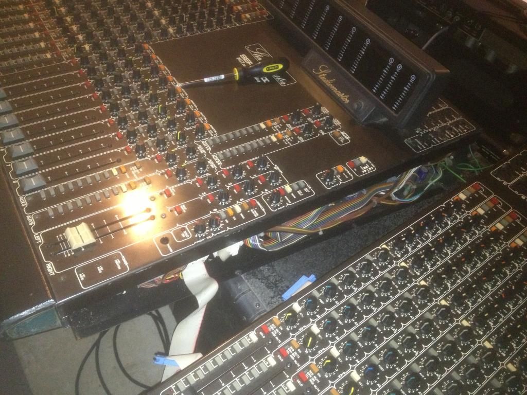
Hope these images work. Not sure if I did it right.
Jed
Hope these images work. Not sure if I did it right.
Jed
-
nag hammadi

- gettin' sounds
- Posts: 136
- Joined: Sat Jul 17, 2010 10:35 pm
Who is online
Users browsing this forum: No registered users and 152 guests