Hello, I have been looking on the net for something to connect a few historic piezo crystal mics to modern inputs. I understand they want a high impedance (10 meg Ohms) input. The (really great!) Avenson small D.I. or the Radial stage bug for piezos come to mind, but I'd like to have these available when tracking a whole band and I'm too broke to buy three more of them right now.
http://www.museweb.com/ag/amp/phantom_fet.jpg
The first one - could I just raise the input Z and mabe omitt the transformer, put in two caps in it's place...
http://www.jensen-transformers.com/as/as004.pdf
I'd like 10 meg instead of 1 meg - and when I understand that halfway, the point where the "J2" output goes into "J3" - J3 could be any transformer isolated mic input with phantom, huh?
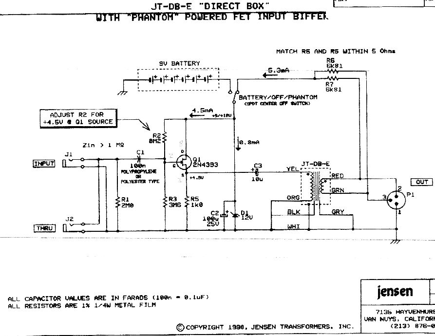
http://www.jensen-transformers.com/as/as098.pdf
on this one I don't understand how phantom power gets to the transistors or, if I don't need isolation, if I can omitt the transformer.
Sorry for having only half a clue, I'm just a cartoonist without proper education in electronics, but willing to sit down, shut up and learn.
phantom powered piezo buffer, 10meg input Z?
https://sites.google.com/site/hpftechllc/
I think he puts schematics up for free
Upright bass stuff since they use piezos a lot.
I think he puts schematics up for free
Upright bass stuff since they use piezos a lot.
-
Scodiddly

- genitals didn't survive the freeze
- Posts: 3974
- Joined: Wed Dec 10, 2003 6:38 am
- Location: Mundelein, IL, USA
- Contact:
If you're OK using a 9v battery instead of phantom power you could build this:
http://www.scotthelmke.com/Mint-box-buffer.html
That's my little project... there are other designs out there too.
http://www.scotthelmke.com/Mint-box-buffer.html
That's my little project... there are other designs out there too.
-
Jim Williams
- tinnitus
- Posts: 1135
- Joined: Sat Jun 03, 2006 8:19 am
- Location: beautiful Carlsbad, CA
- Contact:
The reason is impedance. Piezos are very hign impedance. The input impedance of a Jensen DB tranfomer is 140k. Piezos require about 5 meg ohms.ubertar wrote:Why not look for a suitable transformer? Then you don't have to worry about power, and it will probably sound better.
A jfet buffer will be needed.
Jim Williams
Audio Upgrades
Audio Upgrades
-
ubertar

- ears didn't survive the freeze
- Posts: 3775
- Joined: Wed Feb 18, 2004 7:20 pm
- Location: mid-Atlantic US
- Contact:
The key word there was "suitable". Maybe there's not a suitable transformer currently on the market, but it's technically feasible.Jim Williams wrote:The reason is impedance. Piezos are very hign impedance. The input impedance of a Jensen DB tranfomer is 140k. Piezos require about 5 meg ohms.ubertar wrote:Why not look for a suitable transformer? Then you don't have to worry about power, and it will probably sound better.
A jfet buffer will be needed.
-
Jim Williams
- tinnitus
- Posts: 1135
- Joined: Sat Jun 03, 2006 8:19 am
- Location: beautiful Carlsbad, CA
- Contact:
It's not. You won't get a primary transformer winding to reach that high of an impedance. Internal wiring stray capacitance will eat that up.
If it were possible, Jensen would have already designed it. Connect a capacitive load to a 140k input impedance you will not loose top end, but low end, it will sound as thin as a straw. Unlike resistive loads, capacitive loads eat away at the low end, not the top end like a passive electic guitar.
If it were possible, Jensen would have already designed it. Connect a capacitive load to a 140k input impedance you will not loose top end, but low end, it will sound as thin as a straw. Unlike resistive loads, capacitive loads eat away at the low end, not the top end like a passive electic guitar.
Jim Williams
Audio Upgrades
Audio Upgrades
-
ubertar
- ears didn't survive the freeze
- Posts: 3775
- Joined: Wed Feb 18, 2004 7:20 pm
- Location: mid-Atlantic US
- Contact:
Only if there were enough of a market for it. Jensen is in business to make money.Jim Williams wrote:If it were possible, Jensen would have already designed it.
I'm a pickup maker, not a transformer manufacturer, and not an EE, but there are ways of reducing stray capacitance while optimizing resistance. It would also make the transformer more expensive, both in terms of labor and materials, so not so practical as a commercial product, but still possible. Maybe not so relevant for the OP.
Alternatively, maybe two or even three transformers in series would do the trick.
"There are those who look at things the way they are, and ask why... I dream of things that never were, and ask why not?" -RFK
-
ubertar
- ears didn't survive the freeze
- Posts: 3775
- Joined: Wed Feb 18, 2004 7:20 pm
- Location: mid-Atlantic US
- Contact:
I have some hi-Z ribbon mic transformers that convert 50k ohms to 8 ohms (or vice versa). That's a ratio of 6250:1. Applied to 10 Megohms, that brings it down to 16K. Not quite as far down as you want, but definitely in the ballpark. So I don't think it's unreasonable to expect it to be possible to wind a transformer that would do what you want. It may need to be a bit unconventional in design, but I bet it could be done.
edit: actually the transformers I have are 50k to 5 ohms, not 8. So the ratio is 10,000:1. Applied to 10M, that yields 1K. Even if it was 8 instead of 5, I misplaced the decimal point above... it should have yielded 1.6K instead of 16K. Whether these would sound good or not with the crystal mic, I don't know. But I'd be willing to sell you one for $10 if it's worth the experiment to you.
I suppose there are any number of reasons someone could come up with for why it wouldn't work, but in my experience the only way to really know something is to try it and find out for yourself. When it comes to electronics, I only trust theory so far. That's not because I'm anti-science... I'm not. It's because there are always more variables than get taken into account, and the variables that get left out can have significant effects. Theory, as it gets applied in practice, is often incomplete. This is especially true for electrons, which operate according to quantum mechanics.
Last edited by ubertar on Thu Jun 12, 2014 10:09 am, edited 1 time in total.
-
Jim Williams
- tinnitus
- Posts: 1135
- Joined: Sat Jun 03, 2006 8:19 am
- Location: beautiful Carlsbad, CA
- Contact:
Just the turns ratio would make the output so low it would have less than a microphone.
There are good engineering reasons why this has not been done. A 25 cent jfet fixes all of that, why the resistance to proven designs?
Yes, like any other company, including your's, Jensen is there to make money. Why not call them and ask if they could wind this for you? They do custom work too.
There are good engineering reasons why this has not been done. A 25 cent jfet fixes all of that, why the resistance to proven designs?
Yes, like any other company, including your's, Jensen is there to make money. Why not call them and ask if they could wind this for you? They do custom work too.
Jim Williams
Audio Upgrades
Audio Upgrades
-
ubertar
- ears didn't survive the freeze
- Posts: 3775
- Joined: Wed Feb 18, 2004 7:20 pm
- Location: mid-Atlantic US
- Contact:
Because it's more fun and interesting.Jim Williams wrote:why the resistance to proven designs?
Because I'm not the one who needs this and don't want to waste their time. You don't call and ask for custom work unless you intend to follow through.Jim Williams wrote:Why not call them and ask if they could wind this for you?
-
frans_13

- takin' a dinner break
- Posts: 177
- Joined: Mon Mar 07, 2011 4:46 am
- Location: Bavaria, Germany
- Contact:
As interesting as the idea with a transformer would be, the circumstances don't encourage it. An active part would do the job with less ado. So, on with the thread. I think the Jensen pdf as004 (see post #1) is closest to what I'd want to build. If I use a 10 meg resistor instead of 3.6meg for R2, would that work and raise the input Z to what a piezo needs?
-
Jim Williams
- tinnitus
- Posts: 1135
- Joined: Sat Jun 03, 2006 8:19 am
- Location: beautiful Carlsbad, CA
- Contact:
Who is online
Users browsing this forum: No registered users and 104 guests