phantom powered piezo buffer, 10meg input Z?
-
ubertar

- ears didn't survive the freeze
- Posts: 3775
- Joined: Wed Feb 18, 2004 7:20 pm
- Location: mid-Atlantic US
- Contact:
I don't know what you mean by "because of" there. A step-up transformer converts current into voltage. A step-down transformer, which is what we'd use here, converts voltage into current. So if the piezo has voltage to spare, then reducing the voltage and bumping up the current should not be a problem. At least I don't think so, anyway. I don't have a crystal mic, but I do have plenty of garden-variety piezo transducers. I could wire up the transformer and put it in between the piezo and a mic preamp and see what happens. Either it will work or it won't. That's the beauty of real-world tests vs. theorizing.
-
ubertar
- ears didn't survive the freeze
- Posts: 3775
- Joined: Wed Feb 18, 2004 7:20 pm
- Location: mid-Atlantic US
- Contact:
Hey, so first of all, I hope this isn't annoying anyone, especially the original poster... if so, I could make a new thread for this. Otherwise, I'll keep it here.
Hopefully people will find it interesting.
So I wired the transformer into a box, with a 1/4" input and output, to easily test and compare with versus without. I wired up a piezo disc to a 1/4" plug. I plugged an xlr to 1/4" F adapter into a mic pre input, and taped the piezo to an acoustic guitar. I recorded some strummed chords with and without the transformer in-between. I'm not going to post those results because I want to do it again-- the piezo was making some noise against the guitar. But the results were interesting... the transformer version is fuller in the bass, and the straight version is more trebly. The straight version sounded more natural in a way though, and the transformer version sounded filtered. Neither version sounded "bad", but neither were sounds I'd want as an acoustic guitar track, at least not by itself. Then again, it's just a crappy piezo disc taped to a guitar, so I wouldn't expect much. Anyway, I'll redo the recording and post it so people can make their own judgments.
-
ubertar
- ears didn't survive the freeze
- Posts: 3775
- Joined: Wed Feb 18, 2004 7:20 pm
- Location: mid-Atlantic US
- Contact:
Ok, so here's the result of the transformer test:
http://www.ubertar.com/transformer_test.mp3
All settings are exactly the same, with the exception of adjusting the gain on the preamp. There's no processing whatsoever.
The first 40 seconds are without; the rest is with. To my ears, the transformer version is clearly superior... the straight version is tinny and thin. I still don't think the tranny version sounds great, but it's definitely an improvement. A better test would be the xformer vs. a jfet circuit, but that's more trouble than I feel like going to for this. Bear in mind also that this transformer was not designed for this purpose; it just happens to have a ratio that's fairly close to what we're looking for. It was built with other values in mind, and intended as a step-up rather than a step-down as we're using it for here. Also this is just a cheap piezo disc which is going to be hard to make sound good regardless.
Last edited by ubertar on Sat Jun 14, 2014 4:14 pm, edited 1 time in total.
-
rhythm ranch

- mixes from purgatory
- Posts: 2793
- Joined: Wed May 07, 2003 8:45 pm
- Location: Corrales, NM
Link isn't working.ubertar wrote:Ok, so here's the result of the transformer test:
http://www.ubertar.com/transformer_test
Last edited by rhythm ranch on Thu Nov 05, 2015 3:20 pm, edited 1 time in total.
-
ubertar
- ears didn't survive the freeze
- Posts: 3775
- Joined: Wed Feb 18, 2004 7:20 pm
- Location: mid-Atlantic US
- Contact:
Sorry, I forgot the .mp3 at the end:rhythm ranch wrote:Link is working.ubertar wrote:Ok, so here's the result of the transformer test:
http://www.ubertar.com/transformer_test
http://www.ubertar.com/transformer_test.mp3
-
Zeppelin Design Labs

- audio school graduate
- Posts: 10
- Joined: Wed Nov 04, 2015 10:45 am
- Location: Chicago, Illinois USA
- Contact:
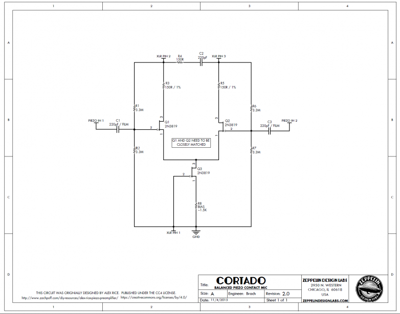
Here's a balanced, buffered piezo mic circuit
This is a pretty interesting discussion of a common problem. Our approach to making piezos really useful is a balancing / buffering circuit, originally designed by <a>Alex Rice</a>. The circuit balances the signal from the piezo for super-quiet signal, and matches the impedance to the recorder's input. You can wire a bunch of piezos in parallel onto one board to combine the signal, like if you want to put several piezos in different places on one instrument.
it does need phantom power though.
I'll dig up the schematic we used and post it.
it does need phantom power though.
I'll dig up the schematic we used and post it.
Last edited by Zeppelin Design Labs on Thu Nov 05, 2015 6:42 am, edited 1 time in total.
-
Jim Williams
- tinnitus
- Posts: 1135
- Joined: Sat Jun 03, 2006 8:19 am
- Location: beautiful Carlsbad, CA
- Contact:
-
Zeppelin Design Labs
- audio school graduate
- Posts: 10
- Joined: Wed Nov 04, 2015 10:45 am
- Location: Chicago, Illinois USA
- Contact:
Pick-a-Piezo
We did try a few piezos and settled on this one for cost, availability and performance. It sounds pretty cool with this circuit. Here's a band we recorded entirely with these mics.
https://soundcloud.com/zeppelin-design- ... ontact-mic
We made a tin can mic for the vocalist, stuck two piezos each on the acoustic guitar and upright base, one on the snare head, and then for the electric guitar we stuck one on the magnet of the Jensen C8R in the 1x8, and one on the side of the cab.
-
Zeppelin Design Labs
- audio school graduate
- Posts: 10
- Joined: Wed Nov 04, 2015 10:45 am
- Location: Chicago, Illinois USA
- Contact:
Cortado schematic
Here's the schematic. The trick is to match the FET's very closely at Q1 & Q2.
-
Jim Williams
- tinnitus
- Posts: 1135
- Joined: Sat Jun 03, 2006 8:19 am
- Location: beautiful Carlsbad, CA
- Contact:
2N3819's are rather old devices, not that quiet compared to newer offerings. You can sub in (or design around) a Linear Systems LSK389 for a matched jfet pair (saves the labor matching JFET's). They are also much lower in noise, about 1 nv/hz/sq.
If lower input capacitance is wanted, they also make the LSK489 matched JFET pair at 4 pf stray capacitance and 1.8 nv noise, still better than the 3819. Then much higher input impedances like 10 meg ohms can be used without losses.
A single package LSK189 can be used as the current source JFET.
www.linearsystems.com
1-800- 359-4023
Jim Williams
Audio Upgrades
Audio Upgrades
-
frans_13

- takin' a dinner break
- Posts: 177
- Joined: Mon Mar 07, 2011 4:46 am
- Location: Bavaria, Germany
- Contact:
After some searching I went with the Cortado and adjusted it to my needs. It does a good job, is super easy to build and I got a few mails of good advice from ZeppelinDesign labs.
To make it work with the high peaks from my DDrum trigger (which I don't use for sound replacing but as a snare shell contact mic) I went for a capacitive divider.
To make it work with the high peaks from my DDrum trigger (which I don't use for sound replacing but as a snare shell contact mic) I went for a capacitive divider.
Who is online
Users browsing this forum: No registered users and 75 guests